Rf22, Data handling and packet handler, Crystal oscillator – Rainbow Electronics RF22 User Manual
Page 23: Regulators, Rx and tx fifos
RF22
Version: 0.1 Date: 12/23/2008
Tel: +86-755-82973805 Fax: +86-755-82973550 E-mail: [email protected] http://www.hoperf.com
23
down to prevent unwanted spectral splatter.
The extra output power can allow use of a cheaper smaller antenna, greatly reducing the overall BOM cost. The higher
power setting of the chip achieves maximum possible range, but of course comes at the cost of higher TX current
consumption. However, depending on the duty cycle of the system the effect on battery life may be insignificant.
Contact HopeRF’s Support for help in evaluating this tradeoff.
Add
R/W
Function/Description
D7
D6
D5
D4
D3
D2
D1
D0
POR Def.
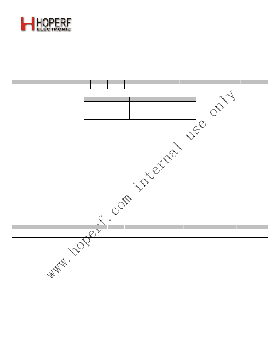
6D
R/W
TX
Power
txpow[1]
txpow[0]
07h
txpow[1:0]
Output Power
00 +11
dBm
01 +14
dBm
10 +17
dBm
11 +20
dBm
5.8. Crystal Oscillator
The RF22 includes an integrated 30 MHz crystal oscillator with a fast start-up time of less than 1 ms. The design is
differential with the required crystal load capacitance integrated on-chip to minimize external components. All that is
required off-chip is the 30 MHz crystal blank.
The crystal load capacitance may be tuned to slightly adjust the frequency of the crystal oscillator. The tuning of the
crystal load capacitance is programmed through the xlc[6:0] field of "Register 09h. 30 MHz Crystal Oscillator Load
Capacitance". The total internal capacitance is 12.5 pF and is adjustable in approximately 127 steps (97fF/step). The
xtalshift bit is a course shift in frequency but is not binary with xlc[6:0]. If AFC is disabled then the synthesizer
frequency may be further adjusted by programming the Frequency Offset field fo[9:0]in "Register 73h. Frequency
Offset 1" and "Register 74h. Frequency Offset 2", as discussed in "3.2.9. Frequency Control" on page 26.
The crystal oscillator frequency is divided down internally and may be output to the microcontroller through one of the
GPIO pins for use as the System Clock. In this fashion, only one crystal oscillator is required for the entire system and
the BOM cost is reduced. The available clock frequencies (i.e., internal division ratios) and the GPIO configuration are
discussed further in "8.2. Microcontroller Clock " on page 54.
The RF22 may also be driven with an external 30 MHz clock signal through the XIN pin.
Add
R/W
Function/Description
D7
D6
D5
D4
D3
D2
D1
D0
POR Def.
09 R/W
Crystal
Oscillator
Load
Capacitance
xtalshift xlc[6] xlc[5
xlc[4] xlc[3] xlc[2]
xlc[1] xlc[0] 40h
5.9. Regulators
There are a total of six regulators integrated onto the RF22. With the exception of the IF and Digital all regulators are
designed to operate with only internal decoupling. The IF and Digital regulators both require an external 1 μF
decoupling capacitor. All of the regulators are designed to operate with an input supply voltage from +1.8 to +3.6 V,
and produce a nominal regulated output voltage of +1.7 V ±5%. The internal circuitry nominally operates from this
regulated +1.7 V supply. The output stage of the PA is not connected internally to a regulator and is connected directly
to the battery voltage.
A supply voltage should only be connected to the VDD pins. No voltage should be forced on the IF or DIG regulator
outputs.
6. Data Handling and Packet Handler
6.1. RX and TX FIFOs
Two 64 byte FIFOs are integrated into the chip, one for RX and one for TX, as shown in Figure 15. "Register 7Fh. FIFO
Access" is used to access both FIFOs. A burst write, as described in "3.1. Serial Peripheral Interface (SPI)" on page 20,