Rf22, Packet configuration, Figure15. fifo thresholds – Rainbow Electronics RF22 User Manual
Page 24
RF22
Version: 0.1 Date: 12/23/2008
Tel: +86-755-82973805 Fax: +86-755-82973550 E-mail: [email protected] http://www.hoperf.com
24
to address 7Fh will write data to the TX FIFO. A burst read from address 7Fh will read data from the RX FIFO.
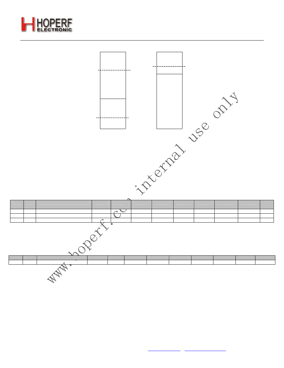
TX FIFORX FIFO
RX FIFO Almost Full
Threshold
TX FIFO Almost Empty
Threshold
TX FIFO Almost Full
Threshold
Figure15. FIFO Thresholds
The TX FIFO has two programmable thresholds. An interrupt event occurs when the data in the TX FIFO reaches
these thresholds. The first threshold is the FIFO Almost Full threshold, txafthr[5:0]. The value in this register
corresponds to the desired threshold value in number of bytes. When the data being filled into the TX FIFO reaches
this threshold limit, an interrupt to the microcontroller is generated so the chip can enter TX mode to transmit the
contents of the TX FIFO. The second threshold for TX is the FIFO Almost Empty Threshold, txaethr[5:0]. When the
data being shifted out of the TX FIFO reaches the Almost Empty threshold an interrupt will be generated. The
microcontroller will need to switch out of TX mode or fill more data into the TX FIFO. The Transceiver may be
configured so that when the TX FIFO is empty the chip will automatically move to the Ready state. In this mode the TX
FIFO Almost Empty Threshold may not be useful. This functionality is set by the ffidle bit in "Register 08h. Operating
Mode and Function Control 2".
Add
R/W Function/Description
D7
D6
D5
D4
D3
D2
D1
D0
POR
Def.
08
R/W Operating & Function Control 2 antdiv[2] antdiv[1]
antdiv[0]
rxmpk autotx enldm ffclrrx ffclrtx 00h
7C
R/W TX FIFO Control 1
txafthr[5]
txafthr[4] txafthr[3]
txafthr[2] txafthr[1] txafthr[0] 37h
7D
R/W TX FIFO Control 2
txaethr[5]
txaethr[4]
txaethr[3]
txaethr[2] txaethr[1] txaethr[0]
04h
The RX FIFO has one programmable threshold called the FIFO Almost Full Threshold, rxafthr[5:0]. When the incoming
RX data reaches the Almost Full Threshold an interrupt will be generated to the microcontroller via the nIRQ pin. The
microcontroller will then need to read the data from the RX FIFO.
Add
R/W
Function/Description
D7
D6
D5
D4
D3
D2
D1
D0
POR ef.
7E
R/W
RX FIFO Control
X
X
rxafthr[5]
rxafthr[4] rxafthr[3] rxafthr[2] rxafthr[1] rxafthr[0]
37h
Both the TX and RX FIFO’s may be cleared or reset with the ffclrtx and ffclrrx bits in "Register 08h. Operating Mode
and Function Control 2". All interrupts may be enabled by setting the Interrupt Enabled bits in "Register 05h. Interrupt
Enable 1" and "Register 06h. Interrupt Enable 2". If the interrupts are not enabled the function will not generate an
interrupt on the nIRQ pin but the bits will still be read correctly in the Interrupt Status registers.
6.2. Packet Configuration
When using the FIFOs, automatic packet handling may be enabled for TX mode, RX mode, or both. "Register 71h.
Modulation Mode Control 2" and "Register 30h. Data Access Control" through "Register 49h. Received Header 1"
control the configuration for Packet Handling. The usual fields for network communication (such as preamble,
synchronization word, headers, packet length, and CRC) can be configured to be automatically added to the data
payload. The fields needed for packet generation normally change infrequently and can therefore be stored in registers.