Rf22, Power amplifier – Rainbow Electronics RF22 User Manual
Page 22
RF22
Version: 0.1 Date: 12/23/2008
Tel: +86-755-82973805 Fax: +86-755-82973550 E-mail: [email protected] http://www.hoperf.com
22
rate can be programmed between 1–128 kbps, and the frequency deviation can be programmed between ±1–160 kHz.
These parameters may be adjusted via registers as shown in "3.2.9. Frequency Control" on page 26.
N
LPF
CP
PFD
Delta-
Sigma
Fref=10M
VCO
TX
Modulation
Selectable
Divider
TX
RX
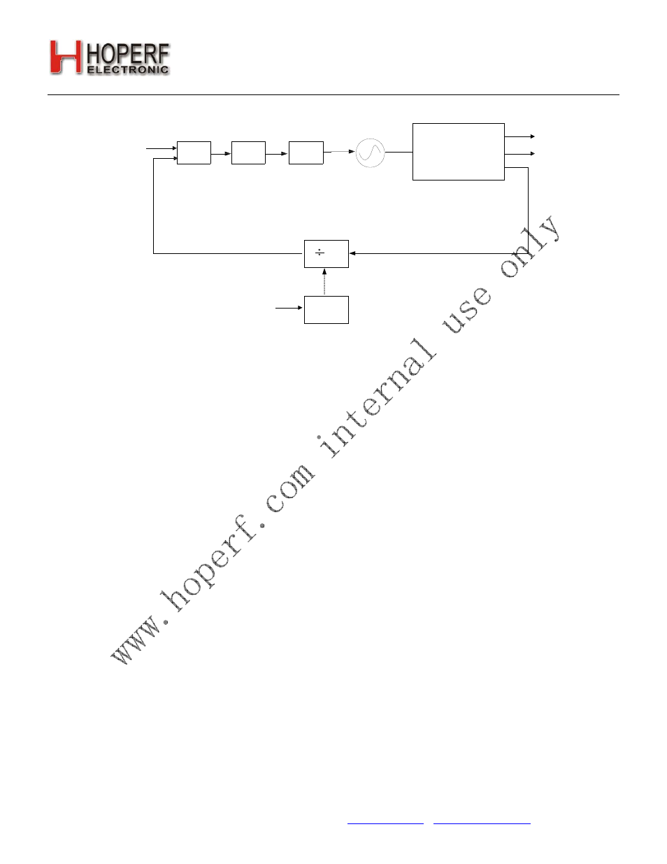
Figure14. PLL Synthesizer Block Diagram
The reference frequency to the PLL is 10 MHz. The PLL utilizes a differential L-C VCO, with integrated on-chip spiral
inductors. The output of the VCO is followed by a configurable divider which will divide down the signal to the desired
output frequency band. The modulus of this divider stage is controlled dynamically by the output from the Σ-Δ
modulator. The tuning resolution of the Σ-Δ modulator is determined largely by the over-sampling rate and the number
of bits carried internally. The tuning resolution is sufficient to tune to the commanded frequency with a maximum
accuracy of 312.5 Hz anywhere in the range between 240–930 MHz.
5.6.1. VCO
The output of the VCO is automatically divided down to the correct output frequency depending on the hbsel and fb[4:0]
fields in "Register 75h. Frequency Band Select". A 2X VCO is utilized to help avoid problems due to frequency pulling,
especially when turning on the integrated Power Amplifier. In receive mode, the LO frequency is automatically shifted
downwards (without reprogramming) by the IF frequency of 937.5 kHz, allowing transmit and receive operation on the
same frequency. The VCO integrates the resonator inductor, tuning varactor, so no external VCO components are
required.
The VCO uses capacitance bank to cover the wide frequency range specified. The capacitance bank will automatically
be calibrated every time the synthesizer is enabled. In certain fast hopping applications this might not be desirable so
the VCO calibration may be skipped by setting the appropriate register.
5.7. Power Amplifier
The RF22 contains an internal integrated power amplifier (PA) capable of transmitting at output levels between +11 to
+20 dBm. The output power is programmable in 3 dB steps through the txpow[1:0] field in "Register 6Dh. TX Power".
The PA design is single-ended and is implemented as a two stage class CE amplifier with efficiency in the range of
45–50% while transmitting at +20 dBm. The efficiency drops to approximately 20% when operating at +11 dBm. Due to
the high efficiency a simple filter is required on the board to filter the harmonics. The PA output is ramped up and down
to prevent unwanted spectral splatter.
5.7.1. Output Power Selection
The output power is configurable in 3 dB steps from +11 dBm to +20 dBm with the txpow[1:0] field in "Register 6Dh. TX
Power". Note that Frequency Hopping (FHSS) is required by the FCC when using an output power level of +20 dBm.
See "8.12. Analog and Digital Test Bus" on page 68 for further information on FHSS. The PA output is ramped up and