Rf22, Internal functional blocks, Rx lna – Rainbow Electronics RF22 User Manual
Page 20: Rx i-q mixer, Programmable gain amplifier, Digital modem, Figure13. fifo mode example
RF22
Version: 0.1 Date: 12/23/2008
Tel: +86-755-82973805 Fax: +86-755-82973550 E-mail: [email protected] http://www.hoperf.com
20
uC
MOSI
MISO
SCK
nSEL
nIRQ
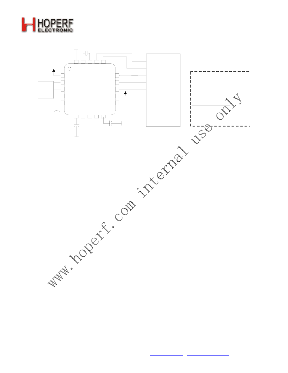
FIFO mode utilizing internal
packet handler. Data loaded/
read through SPI into FIFO .
GPIO configuration
Not Utilized
VDD_RF
TX
RXp
RXn
SCLK
SDI
SDO
VDD_DIG
AD
C_REF
GPI
O
_
0
XIN
XOUT
SDN
nIRQ
VR_IF
GND_DIG
VR
_D
IG
nSEL
Matching
GPI
O
_
1
GPI
O
_
2
Figure13. FIFO Mode Example
5. Internal Functional Blocks
This section provides an overview some of the key blocks of the internal radio architecture.
5.1. RX LNA
The input frequency range for the LNA is 240–930 MHz. The LNA provides gain with a noise figure low enough to
suppress the noise of the following stages. The LNA has one step of gain control which is controlled by the analog gain
control (AGC) algorithm. The AGC algorithm adjusts the gain of the LNA and PGA so the receiver can handle signal
levels from sensitivity to +5 dBm with optimal performance.
5.2. RX I-Q Mixer
The output of the LNA is fed internally to the input of the receive mixer. The receive mixer is implemented as an I-Q
mixer that provides both I and Q channel outputs to the complex IF filter. The mixer consists of two doublebalanced
mixers whose RF inputs are driven in parallel, local oscillator (LO) inputs are driven in quadrature, and separate I and
Q Intermediate Frequency (IF) outputs drive the complex filter. The receive LO signal is supplied by an integrated VCO
and PLL synthesizer operating between 240–930 MHz. The necessary quadrature LO signals are derived from the
divider at the VCO output.
5.3. Programmable Gain Amplifier
The Programmable Gain Amplifier (PGA) provides the necessary gain to boost the signal level into the Dynamic Range
of the ADC. The PGA must also have enough gain switching to allow for large input signals to ensure a linear RSSI
range up to –30 dBm. The PGA is designed to have steps of 3 dB which are controlled by the AGC algorithm in the
digital modem.
5.4. ADC
The amplified I&Q IF signals are digitized using an Analog-to-Digital Converter (ADC), which allows for low current
consumption and high dynamic range. The bandpass response of the ADC provides exceptional rejection of out of
band blockers.
5.5. Digital Modem
Using high-performance ADCs allows channel filtering, image rejection, and demodulation to be performed in the
digital domain, resulting in reduced area while increasing flexibility. The digital modem performs the following functions:
■
Channel Selection Filter
■
TX Modulation