Rf22, Figure8. state machine diagram, Table11. operating modes – Rainbow Electronics RF22 User Manual
Page 10
RF22
Version: 0.1 Date: 12/23/2008
Tel: +86-755-82973805 Fax: +86-755-82973550 E-mail: [email protected] http://www.hoperf.com
10
The output of the LPLDO is internally connected in parallel to the output of the main digital regulator (and is available
externally at the VR_DIG pin); this common digital supply voltage is connected to all digital circuit blocks, including the
digital modem, crystal oscillator, and SPI and register space. The LPLDO has extremely low quiescent current
consumption but limited current supply capability; it is used only in the IDLE-STANDBY and IDLE-SLEEP modes.
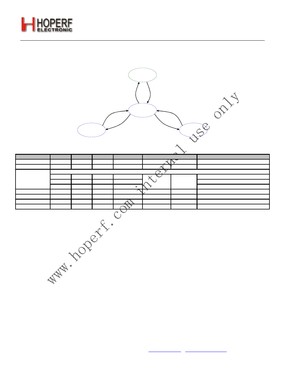
SHUT DWN
IDLE*
TX
RX
*Five Different Options for IDLE
Figure8. State Machine Diagram
Table11. Operating Modes
State/Mode
xtal
pll
wt
LBD or TS
Response time to
Current in State /Mode [μA]
TX
RX
Shut Down State
X
X
X
X
16.21 ms
16.21 ms
0 0 0 0
400
nA
0 0 1 0
800
nA
Idle States:
Standby Mode
Sleep Mode
Sensor Mode
0 0 X 1
1.21 ms
1.21 ms
1 μA
Ready
Mode
1 0 X X
210
μs 210
μs 600
μA
Tune
Mode
1 1 X X
200
μs 200
μs 9.5
mA
TX
State 1 1 X X
NA
200
μs
60 mA @ +20 dBm, 27 mA @ +11 dBm
RX
State 1 1 X X
200
μs NA 18.5
mA
3.2.1. Shutdown State
The shutdown state is the lowest current consumption state of the device with nominally 5 nA of current consumption.
The shutdown state may be entered by driving the SDN pin (Pin 20) high. The SDN pin should be held low in all states
except the SHUTDOWN state. In the SHUTDOWN state, the contents of the registers are lost and there is no SPI
access.
When the chip is connected to the power supply, a POR will be initiated after the falling edge of SDN.
3.2.2. Idle State
There are five different modes in the IDLE state which may be selected by "Register 07h. Operating Mode and
Function Control 1". All modes have a tradeoff between current consumption and response time to TX/RX mode. This
tradeoff is shown in Table 11. After the POR event, SWRESET, or exiting from the SHUTDOWN state the chip will
default to the IDLE-READY mode. After a POR event the interrupt registers must be read to properly enter the SLEEP,
SENSOR, or STANDBY mode and to control the 32 kHz clock correctly.
3.2.2.1. STANDBY Mode
STANDBY mode has the lowest current consumption possible with only the LPLDO enabled to maintain the register
values. In this mode the registers can be accessed in both read and write mode. The standby mode can be entered by
writing 0h to "Register 07h. Operating Mode and Function Control 1". If an interrupt has occurred (i.e., the nIRQ pin = 0)
the interrupt registers must be read to achieve the minimum current consumption. Additionally, the ADC should not be
selected as an input to the GPIO in this mode as it will cause excess current consumption.