Rf22, Enmanch rb fd h + ч ч = 1 2, Ч + + ч = fd enmanch rb bw 2 1 2 – Rainbow Electronics RF22 User Manual
Page 30: Fd enmanch rb bw + + × = 1, 2bw bw bw f, Fbw bw ferror, Fbw bw
RF22
Version: 0.1 Date: 12/23/2008
Tel: +86-755-82973805 Fax: +86-755-82973550 E-mail: [email protected] http://www.hoperf.com
30
10
40
8.00
90
0
0
3
190
051EC
02B
19.2
9.6
1.00
37.7
0
1
1
068
13A93
4EE
20
10
1.00
37.7
0
1
1
064
147AE
521
20
40
4.00
95.3
0
0
4
0C8
0A3D7
0A6
38.4 19.6
1.02
75.2
0
0
1
068
13A93
4D5
40
20
1.00
75.2
0
0
1
064
147AE
521
40
40
2.00
112.1
0
0
5
064
147AE
291
50
25
1.00
75.2
0
0
1
050
1999A
668
57.6 28.8
1.00
90
0
0
3
045
1D7DC
76E
100
50
1.00
191.5
1
0
F
078
11111
446
100
300
6.00
620.7
1
0
E
078
11111
0B8
125
125
2.00
335.5
1
0
8
060
15555
2AD
7.1.1. Advanced FSK and GFSK Settings
In nearly all cases, the information in Table 16, “RX Modem Configurations for FSK and GFSK,” on page 47 can be
used to determine the required FSK and GFSK modem parameters. The section includes a more detailed discussion of
the various modem parameters to allow for experienced designers to further configure the modem performance.
In FSK or GFSK mode the receiver can handle a wide range of modulation indices ranging from 0.5 up to 32. The
modulation index (h) is defined by the following:
(
)
enmanch
Rb
Fd
h
+
Ч
Ч
=
1
2
When the modulation index is 1 or higher the modulation bandwidth can be approximated by the following equation:
(
)
⎟
⎠
⎞
⎜
⎝
⎛
Ч
+
+
Ч
=
Fd
enmanch
Rb
BW
2
1
2
mod
When the modulation index is lower than 1 the modulation bandwidth can be approximated by the following:
(
)
(
)
Fd
enmanch
Rb
BW
+
+
×
=
1
mod
Where BW
mod
is an approximation of the modulation bandwidth in kHz, Rb is the payload bit rate in kbps, Fd is the
frequency deviation of the received GFSK/FSK signal in kHz and enmanch is the Manchester Coding parameter (see
Reg. 70h, enmach is 1 when Manchester coding is enabled, enmanch is 0 when disabled).
The bandwidth of the channel select filter in the receiver might need some extra bandwidth to cope with tolerances in
transmit and receive frequencies which depends on the tolerances of the applied crystals. When the relative frequency
error (F
error
) between transmitter and receiver is less than half the modulation bandwidth (BW
mod
) then the AFC will
correct the frequency error without needing extra bandwidth. When the frequency error exceeds BW
mod
/2 then some
extra bandwidth will be needed to assure proper AFC operation under worst case conditions. When the AFC is enabled
it is recommended to set the bandwidth of the channel select filter (BW
ch-sel
) according to the formulas below:
mod
mod
2
BW
BW
BW
F
sel
ch
error
=
⇒
≤
−
error
sel
ch
F
BW
BW
Ferror
×
=
⇒
>
−
2
2
mod
When the AFC is disabled it is recommended to set the bandwidth of the channel select filter (BW
ch-sel
) according to
the following:
error
sel
ch
F
BW
BW
×
+
=
−
2
mod
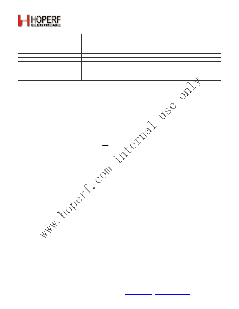
When the required bandwidth (BW) is calculated then the three filter parameters, ndec_exp, dwn3_bypass and filset,
can be found from the table below. When the calculated bandwidth value is not exactly available then select the higher
available bandwidth closest to the calculated bandwidth.