Figure 8 – M&C TechGroup CSS-VC2 Operator's manual User Manual
Page 22
22
Gas sampling and gas conditioning technology
14.1a-ME
12.4.2 CONNECTION OF INDIVIDUAL ALARMS, EXTERNAL PUMP CONTROL AND
EXTERNAL COOLER TEMPERATURE DISPLAY (ART. NO. 01G6175)
The electrical connection of the individual alarms is via two connectors, depending on the mounting of
the connection plate, either on the back or in the lid of the housing.
The corresponding 11 and 12-pin connectors are included.
The connectors are assigned as follows:
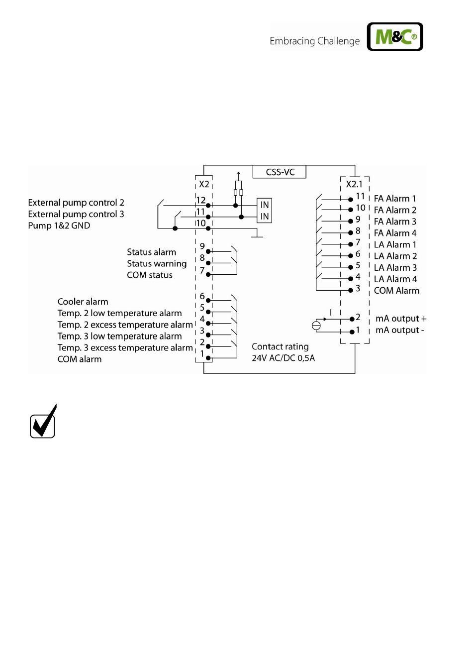
Figure 8
Plug assignment for design with individual alarms (Art. No. 01G6175)
N O T I C E !
For the alarm relays „safety first“ is valid, i.e. contacts are open
currentless and in case of alarm.
For external pump control potential free contacts have to be used!
Switch open => pump off
Switch closed => pump on
On X2 connector pin 10-12, external switches can be connected for controlling the sample gas pumps
(internal or external).
On X2 connector pin 7+8, an indicator can be connected that warning messages are present (yellow
LED lights up on the front of the TCU).
On X2 connector pin 7+9, an indicator can be connected that alarm messages are present (red LED
lights up on the front of TCU).
On X2 connector pin 1+6, an indicator can be connected that a cooler temperature alarm is present
(excess or low temperature alarm).
On connector X2 pin 1+2, 1+3, 1+4, 1+5, an indicator can be connected that excess or low
temperature alarms of the optional temperature controller module are present.