Supply connections, Figure 3, Connections in the connection panel of the css-vc – M&C TechGroup CSS-VC2 Operator's manual User Manual
Page 18: Figure 4, Connection group alarm, 12 supply connections
18
Gas sampling and gas conditioning technology
14.1a-ME
12
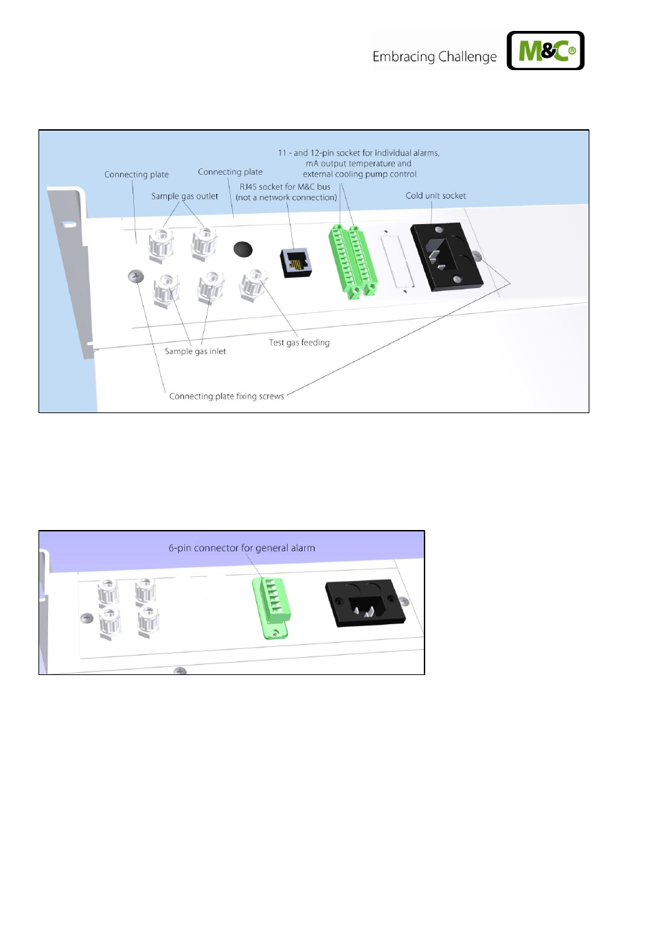
SUPPLY CONNECTIONS
Figure 3
Connections in the connection panel of the CSS-VC..
Depending on the version of the CSS-VC, instead of the 11 and 12-pin connector for single alarms,
mA output cooler temperature and external sample gas pump control, a 6-pin connector may also be
present for group alarm (see Figure 4 ). The sample gas inlet, depending on the version, may also lie
directly on the heat exchangers.
Figure 4
Connection group alarm
In the portable version of the CSS-VC.., the supply connectors shown above are located on the rear
panel of the housing. The RJ45 connector is not present here. With the temperature controller option
for the portable version (Art. No. 01G6190), a 7-pin connector (see section 0) is present at the position
of the RJ45 connector in Figure 3.
- SP10 Operator's manual (14 pages)
- N9 KP18 Operator's manual (21 pages)
- SP2000_20SS 150 Data sheet (3 pages)
- SP3100 Data sheet (6 pages)
- PSP4000-H _C _T Data sheet (4 pages)
- SP2200-H_C_I_BB_F Data sheet (2 pages)
- SP35-H... for gas sample probe SP2000-H... Data sheet (2 pages)
- FP-BF Data sheet (2 pages)
- SP3200 Operator's manual (28 pages)
- FPF-0,1 Operator's manual (2 pages)
- PSS-10_1 Operator's manual (23 pages)
- CSS-V2 Data sheet (3 pages)
- PMA 50 EEX Operator's manual (48 pages)
- MP30 Operator's manual (18 pages)
- SP2600-H_C_I_BB_F_0,1GF190 Data sheet (3 pages)
- SR25.1_Ex Operator's manual (22 pages)
- PMA 10S Operator's manual (27 pages)
- CSS-M_W Data sheet (3 pages)
- PAS-500 Operator's manual (20 pages)
- SP2000H320_DIL... Data sheet (3 pages)
- SP3200 Data sheet (6 pages)
- FA-1_2_3,bi Operator's manual (24 pages)
- SR25 Data sheet (2 pages)
- SP3000 Data sheet (4 pages)
- PAS Series Data sheet (2 pages)
- CG Series Data sheet (2 pages)
- ECP 20-2 Data sheet (3 pages)
- MP30-EX Data sheet (2 pages)
- PSP4000-H_C_T Operator's manual (24 pages)
- DIL-U Data sheet (2 pages)
- ADS-So Data sheet (2 pages)
- VC-2-SL Operator's manual (18 pages)
- ECM-ExII Operator's manual (39 pages)
- MP12 Operator's manual (17 pages)
- FPF+ Data sheet (2 pages)
- KS 2.Ex Operator's manual (17 pages)
- PMA 50 EEX Data sheet (3 pages)
- PMA 10S Data sheet (3 pages)
- Gas Sample Probes Series SP Data sheet (2 pages)
- BA-C Operator's manual (16 pages)
- MV3_2-H Series Operator's manual (18 pages)
- VC-2-SL Data sheet (3 pages)
- FM-200K-H_FA Operator's manual (16 pages)
- SP 30-H.._EX2 Operator's manual (16 pages)
- SP2006-H280_DIL Operator's manual (35 pages)