Chapter 2 hardware installation & initial setup, 1 front panel leds – ZyXEL Communications 480 User Manual
Page 31
Prestige 480 ISDN Router
Hardware Installation and Setup
2-1
Chapter 2
Hardware Installation & Initial Setup
This chapter shows you how to make the cable connections to your
Prestige as well as set up your ISDN connection using the SMT.
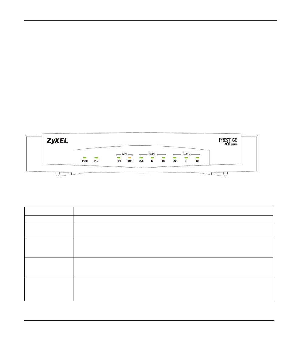
2.1 Front Panel LEDs
The LED indicators on the front panel indicate the router functional status of the Prestige. The
following table describes the LED functions:
Figure 2-1 Front Panel
Table 2-1 LED Functions
Field
Description
PWR
The PWR (power) LED is on when power is applied to the Prestige.
SYS
The SYS (System) LED is on when the system is running normally, and off when the
system is not ready or failed. It flashes when the system is rebooting.
LAN 10M
This green LED is on when the 10M Ethernet is connected and ready and off when
the 10M Ethernet is not ready or failed. This LED flashes when the Prestige is
sending or receiving packets.
100M
This orange LED is on when the 100M Ethernet is connected and ready and off
when the 100M Ethernet is not ready or failed. This LED flashes when the Prestige
is sending or receiving packets.
ISDN 1 & 2 LNK
B1/B2
The LNK (Link) LED is on when the Prestige is connected to an ISDN switch and
the line has been successfully initialized; otherwise, it is off.
The B1/B2 LED is on when the corresponding B Channel is in use.