Port number – Toshiba Strata DK 16 User Manual
Page 84
PROGRAMMING PROCEDURES-INSTRUCTIONS/SYSTEM RECORDS
SECTION 100-816-302
MARCH 1993
2-60
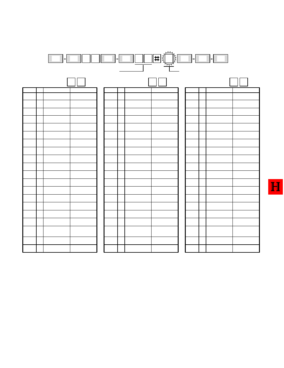
PROGRAM 20
DATA INTERFACE UNIT (DIU) PORT CONFIGURATION
H
Z
Z
2
P
S
H
S
0
Button/LEDs1 ~ 5 defines data port type;
Button/LEDs 17 ~ 20 assigns data port to
security group.
Select =
Logical Port Number that is connected to
PDIU-DS or to DKT with PDIU-DI(2).
LED
X
LED ON
LED OFF
Data Security
Group 4
Data Security
Group 2
Data Security
Group 3
Data Security
Group 1
PDIU-DS
Connected
PDIU-DS to
Modem
Connection
AT Commands
and Result Codes
DIU
Connected
Not
Included
PDIU-DI(2)6
Connected
PDIU-DS to other
type DCE or DTE
AT Dial
Command Only
No DIU
Connected
20
19
18
17
16
15
14
13
12
11
10
09
08
07
06
05
04
03
02
01
Port Number
Not
Included
Not
Included
Not
Included
Auto Pause3
Behind PBX
No Auto
Pause
DTR Pulse With5
Data Release
No DTR
Pulse
NOTES:
1. For more information, see the instructions preceding the record sheets. Copy this page if more than three DIUs are installed.
2. Initialized data: LED 17 ON, all others OFF.
3. Auto pause will be inserted after a Centrex or PBX access code is dialed by a DIU: CO line must be assigned in Program
42-0 and must have access code assigned in Program 42 (1 ~ 8). Pause time is determined by Program 12-3. A pause will
also be inserted after the DK CO line access code is dialed (by the DIU) in all cases if LED 05 is turned on.
4. DIUs can connect to any digital circuit in the Base Unit and on the PDKU2 and KCDU, but it can only connect to Circuits 1
~ 7 on the PDKU1.
5. If a PDIU-DS is connected to a modem, turn LED 06 ON to cause the modem to disconnect the line when the user presses
the Data Release button. Modem should be sent AT Command “AT & D2” so it can recognize DTR pulse, and the PDIU-DS
SW1-2 switch must be off (in the up position). This feature is for outgoing modem calls only—DTR will not pulse on incoming
modem calls. Always change the modem escape sequence from “+ + +” to some other character using the “ATS2=____”
command; this allows AT commands to be sent to the modem or DIU independently.
6. The PDIU-DI connects to 1000-series Digital Telephones, and the PDIU-DI2 connects to 2000-series Digital Telephones.