Spreadsheet view: pcb layers tab, Spreadsheet view: parts position tab – National Instruments Graphical User Interface Ultiboard User Manual
Page 61
Chapter 1
User Interface
© National Instruments Corporation
1-45
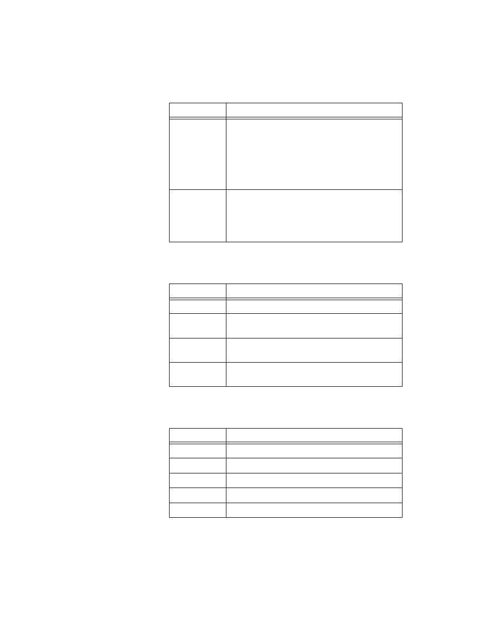
Spreadsheet View: PCB Layers Tab
Use the PCB Layers tab to work with layer information.
Spreadsheet View: Parts Position Tab
Use the Parts Position
tab to view and export part position information.
Part Group
Double-click to display the Select Groups dialog
box, where you select the part group to which you
wish to assign the Keep-in/out. You can also set this in
Keep-in/Keep-out Properties dialog box. Refer to
the
Working with Keep-in/Keep-out Areas
section of
Working with Traces and Copper
information.
Heights
Bigger Than
Assign a height (z-axis) value to theKeep-in/out. Can be
entered directly, or in the Keep-in/Keep-out
Properties dialog box. Refer to the
, for more information.
Column
Description
Layer Name
The name of the layer, for example, Copper Top.
Routable
Select Yes to allow trace routing on the layer; select
No to prevent trace routing on the layer.
Trace Bias
Set the trace bias by selecting Horizontal, Vertical or
None.
Type
The type of layer. Choices are Ground, Power,
Signal or Unassigned.
Column
Description
RefDes
The part’s Reference Designator.
Position X
The part’s position on the X axis.
Position Y
The part’s position on the Y axis.
Side
The side of the PCB on which the part appears.
Rotation
The orientation of the part on the PCB.
Column
Description