Pads/vias tab, Pads/vias tab -22 – National Instruments Graphical User Interface Ultiboard User Manual
Page 38
Chapter 1
User Interface
1-22
ni.com
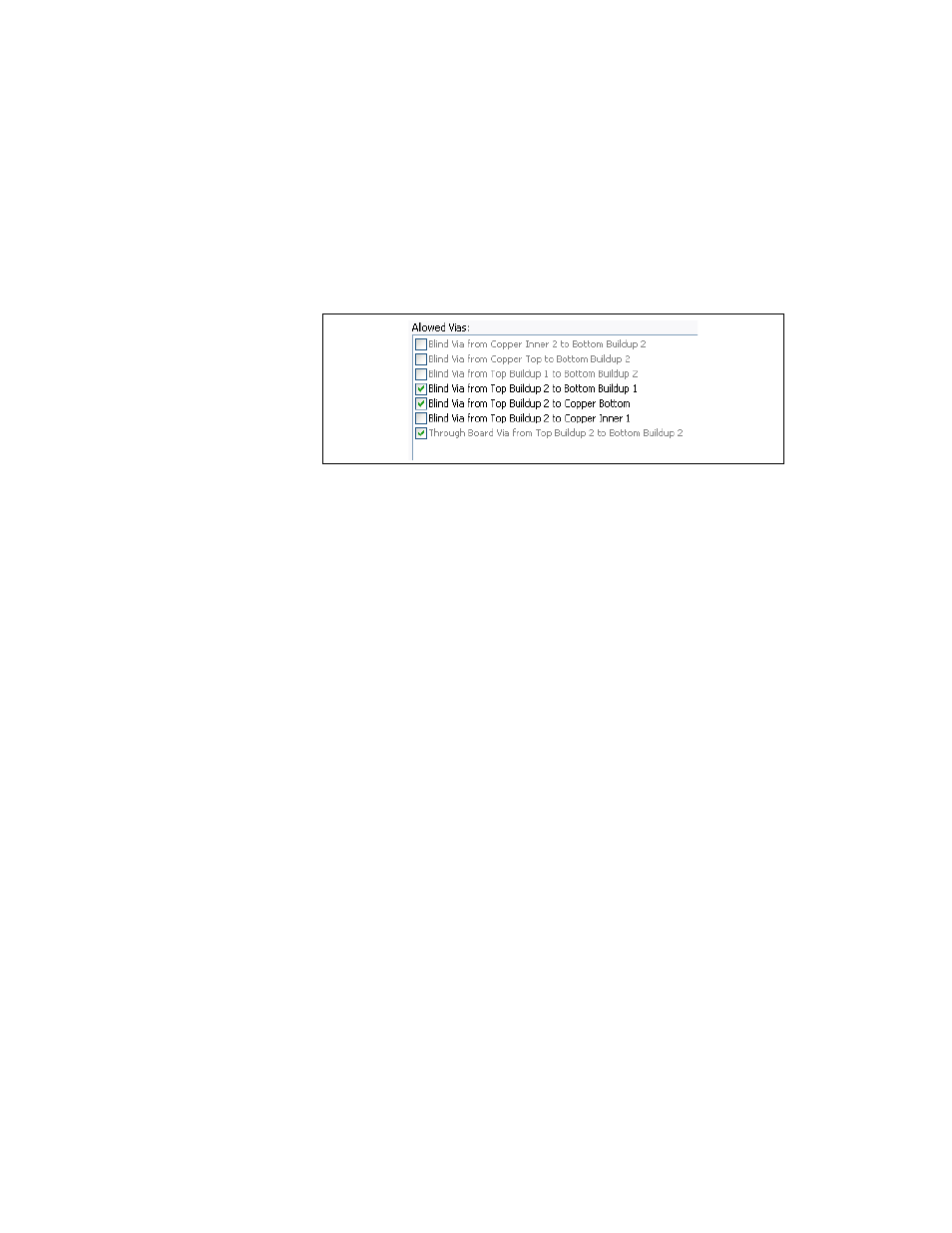
4.
As you make changes to the layer settings, the Allowed Vias pane
shows the acceptable layer combinations for blind and buried vias or
microvias. Use the checkboxes to select the layer combinations you
want to allow in your design as shown in the example in the figure
below.
5.
In the Allow Routing area, from the Copper Layer drop-down list,
select the copper layer for which you wish to assign routing properties
and click Properties to display the Copper Layer Properties dialog
box.
Enable the Routable checkbox to allow routing on the selected layer.
In the Trace Bias drop-down list, select one of Horizontal; Vertical;
or None.
Click OK to close the Copper Layer Properties dialog box.
6.
In the Board area, enter the desired Board Outline Clearance and
Board Thickness.
7.
Click OK to close the dialog box.
Pads/Vias Tab
Use the Pads/Vias tab of the PCB Properties dialog box to set the
following:
•
•
•
•
•