Centered stripline trace calculations, Centered stripline trace calculations -4 – National Instruments Graphical User Interface Ultiboard User Manual
Page 187
Chapter 6
PCB Calculators
6-4
ni.com
Embedded Microstrip Equations
The equations used to perform the embedded microstrip calculations are:
Z0 = 56*ln(5.98*H/(0.8*W+T))/sqrt(Er*(1-exp(-1.55*H1/H)))
Tpd = 84.66667*sqrt(Er*(1-exp(-1.55*H1/H)))
C0 = Tpd/Z0
L0 = C0*Z0*Z0
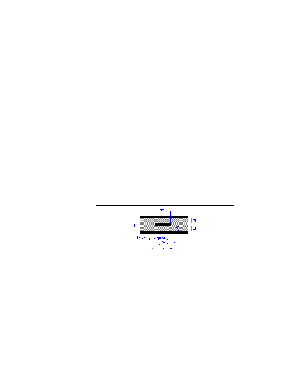
Centered Stripline Trace Calculations
Complete the following steps to perform centered stripline trace
calculations:
1.
Select Tools»PCB Transmission Line Calculator.
2.
Select Centered Stripline in the Type drop-down list.
3.
In the Input Data area, edit the following fields as desired:
•
Input Length Unit—Select mils or millimeters.
•
Dielectric Thickness (H)—Refer to the figure below.
•
Trace Thickness (T)—Refer to the figure below.
•
Trace Width (W)—Refer to the figure below.
•
Relative Permittivity (epsilon r)—Refer to the figure below.
4.
Click Calculate. Results of the calculation appear in the Calculation
Results area. They also appear in the Results tab of the Spreadsheet
View.
5.
Click Close to close the PCB Transmission Line Calculator.