Changing configuration options, Selecting the g.703 dte or data port for led, Display – Paradyne ACCULINK 336x E1 User Manual
Page 32: Section later in this chapter to choose which port
Operation
3-11
3360-A2-GB20-20
December 1996
Selecting the G.703 DTE or
Data Port for LED Display
Use the LED command on the Control branch to select
which port’s (G.703 DTE or data port) status appears on
the five shared LEDs on the front panel.
NOTE
The following procedure is an
example only. Screen displays
may vary depending on the
model and configuration of the
E1 NTU.
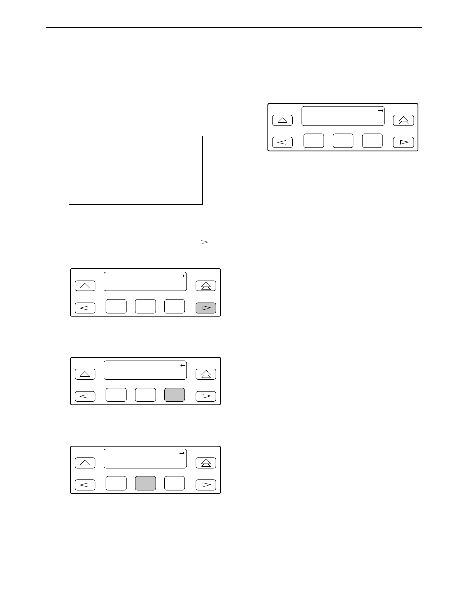
To select a port for LED display,
1. From the top-level menu screen, press the
key
until the Ctrl selection appears on the screen.
F1
E1 HDSL NTU
Stat
Test
Cnfig
F2
F3
2. Select Ctrl.
F1
E1 HDSL NTU
Test
Cnfig
Ctrl
F2
F3
3. From the Control screen, select LED.
F1
Control:
Rel
LED
ClrReg
F2
F3
The currently selected port name appears on the
top line of the LCD. DTE indicates the G.703
DTE port.
F1
LED Dsply: DTE
DTE
Prt1
Prt2
F2
F3
4. From the LED Dsply screen, press the Function
key that corresponds to the G.703 DTE or data
port for which you want the LEDs to display. Use
the scroll keys, if necessary.
Select DTE to monitor the G.703 DTE port’s SIG,
OOF, ALRM, PDV, and BPV status signals on the
shared LEDs.
Select a particular data port to monitor the data
port’s DTR, TXD, RXD, CTS, and RTS control
signals on the shared LEDs.
Changing Configuration
Options
The E1 NTU is an intelligent device that displays only
valid options for the current configuration. Therefore, you
are only presented with menu choices that are consistent
with the current configuration and operational state of the
E1 NTU; invalid combinations of configuration options
do not appear. For example, menus displayed for the
Model 3360 (2 ports) and the Model 3364 (4 ports) differ
due to the number of ports available. Also, if the G.703
DTE interface selection is disabled, many of the menu
choices do not appear. Be aware that although all options
are shown in this guide, what you see on your E1 NTU
varies with your configuration.
The E1 NTU offers four sets of configuration options
located in the following memory areas:
•
Active (Activ). The configuration option set active
for the E1 NTU is stored here. Before a
configuration option set becomes active for the E1
NTU, you must save the set to the Active area.
When the E1 NTU is shipped from the factory, the
Active configuration option set is identical to the
Factory set. This area can be written to and controls
the current operation of the device.