Patton electronic G.SHDSL INTEGRATED 3086 User Manual
Page 41
V.35 and X.21 Ports
41
Model 3086 G.SHDSL Integrated Access Device User Guide
4 • Basic Application Configurations
Switch configuration: Switch configuration in the 3086 is to be used in situations where the 3086 functions as
a DSL modem carrying TDM (X.21, V.35) data only, without resorting to the use of a PC for configuration.
When configuring the Model 3086 via DIP switches, the following conditions apply:
•
Speed selected applies to the Sync Serial port, not to the Ethernet port
•
PCM Mode will be set to Serial only
•
DSL interface will be set to HDLC
•
To enable DIP witch operation, begin by setting up the DSL rate (units are shipped with switches in the On
position —corresponding to CLI/Web management).
•
Implementation of DIP switch settings can be done in two ways:
-
Set up DIP switches and then cycle power On/Off/On.
-
Set up DIP switches and then turn the implementation switch (S2-8) to the Off position, wait 3 to 4 sec-
onds, turn S2-8 back to On (you do not need to cycle the power for the unit).
•
To put the unit back to CLI/Web management, ALL DIP switches must be set to the On position.
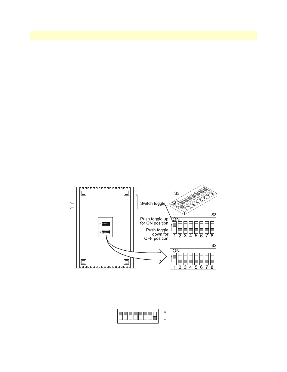
The Model 3086 includes two eight-DIP switch banks labeled S2 and S3. They are externally accessible by
removing the plate on the bottom side of the unit. Figure 8 shows the location of the DIPswitches on the bot-
tom of the printed circuit board.
Figure 8. DIP switches location
DIP switches S2 and S3 can be configured as either “On” or “Off”. Figure 9 shows the orientation of the DIP
switches with respect to the ON/OFF positions.
Figure 9. Close-up of DIP switches showing ON/OFF positions
1
2
3
4
5
6
7
8
ON
ON
OFF