Patton electronic G.SHDSL INTEGRATED 3086 User Manual
Page 20
1 • General Information
Model 3086 G.SHDSL Integrated Access Device User Guide
20
Model 3086 G.SHDSL IAD overview
The test mode switches are:
•
Normal, Local, and Remote Loopbacks
•
Normal, 511, and 511E pseudo-random bit patterns
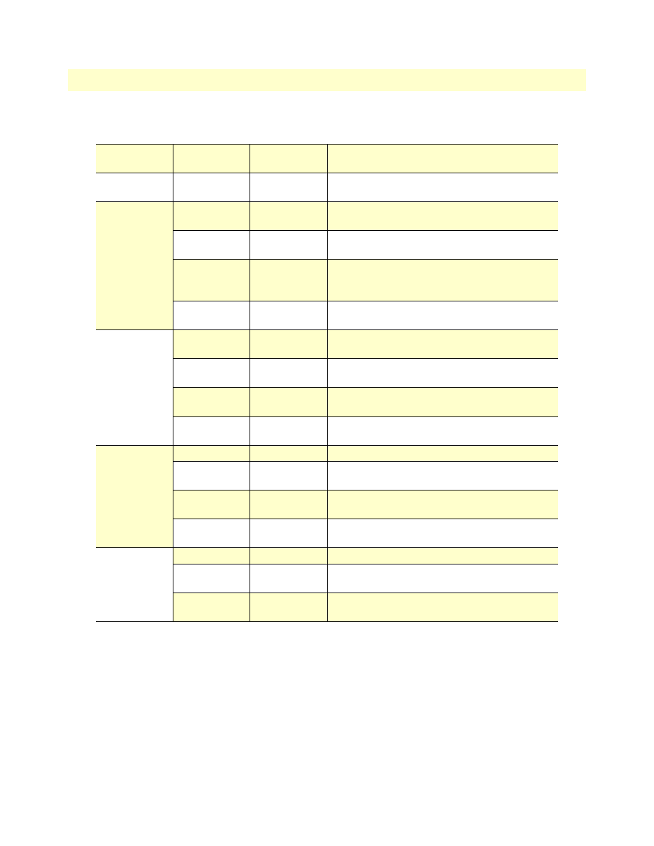
Table 3. Status LED descriptions
Power
Green
ON indicates that power is applied. Off indicates
that no power is applied.
WAN (DSL)
Link
Green
Solid green: connected
Off: disconnected
Sync Serial
TD
Green
Green: indicates a binary ‘0’ condition
off: indicates a binary ‘1’or idle condition
RD
Green
Green: indicates a binary ‘0’condition
off: indicates a binary ‘1’ or idle condition
CTS
Green
ON: indicates the CTS signal from the IAD is
active, binary ‘1’
off: indicates CTS is binary ‘0’
DTR
Green
ON: indicates the DTR signal from the DTE device
attached to the serial port is active, binary ‘1’
T1/E1
Link
Green
On: indicates the T1/E1 interface is connected to a
live T1/E1 line
LOS
Red
On: indicates a T1/E1 loss-of-frame condition. It
also indicates that no T1/E1 signal is detected.
TD
Green
Green: indicates a binary ‘0’ condition
off: indicates a binary ‘1’or idle condition
RD
Green
Green: indicates a binary ‘0’condition
off: indicates a binary ‘1’ or idle condition
Ethernet
Link
Green
ON: indicates an active 10/100 BaseT connection
100M
Green
ON: connected to a 100BaseT LAN
Off: connected to a 10BaseT LAN
Tx
Green
Flashing: when transmitting data from the IAD to
the Ethernet
Rx
Green
Flashing: when transmitting data from the Ethernet
to the IAD.
Status
NS
Red
ON: incidates absence of a valid DSL connection
ER
Red
flashes once: indicates bit errors occurring during
511/511E tests
TM
Yellow
ON: is under one of the test modes (local loop,
remote loop, or V.54 BER pattern)