Connector definitions and pin-outs, 1 main power connector – Intel SE7525GP2 User Manual
Page 146
Intel® Server Board SE7320SP2 & Intel Server Board SE7525GP2 TPS Connector Definitions and Pin-Outs
Revision 2.0
146
7. Connector Definitions and Pin-Outs
7.1 Main Power Connector
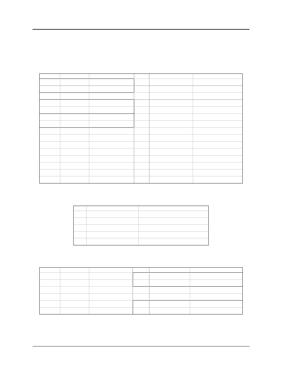
The main power supply connection is obtained using the 24-pin connector. The following table
defines the pin-outs of the connector.
Table 69. Power Connector Pin-out (J12)
Pin
Signal
18 AWG Color
Pin
Signal
18 AWG Color
1* +3.3VDC
Orange 13
+3.3VDC
Orange
3.3V RS
Orange (24AWG)
14 -12VDC
Blue
2 +3.3VDC
Orange
15
COM
Black
3* COM Black
16
PSON#
Green
COM RS
Black (24AWG)
17 COM
Black
4* +5VDC Red
18
COM
Black
5V RS
Red (24AWG)
19 COM
Black
5 COM Black
20
Reserved
N.C.
6 +5VDC
Red
21
+5VDC
Red
7 COM Black
22
+5VDC
Red
8 PWR
OK
Gray
23
+5VDC
Red
9 5
VSB Purple
24
COM
Black
10 +12V3 Yellow
11 +12V3 Yellow
12 +3.3VDC
Orange
Table 70. Auxiliary Signal Connector (J5)
Pin
Signal
24 AWG Color
1 I2C
Clock
White
2
I2C Data
Yellow
3 Reserved
N.C.
4 COM
Black
5 3.3RS
Orange
Table 71. Auxiliary CPU Power Connector Pin-out (J22)
Pin
Signal
18 AWG color
Pin
Signal
18 AWG Color
1 COM Black
5*
+12V1
White
2 COM Black
12V1 RS
Yellow (24AWG)
3 COM Black
6
+12V1
White
4 COM Black
7
+12V2
Brown
8*
+12V2
Brown
12V2 RS
Yellow (24AWG)