Platform management, 6300esb, 8742x sio – Intel SE7525GP2 User Manual
Page 104: Heceta 7
Intel® Server Board SE7320SP2 & Intel Server Board SE7525GP2 TPS
Platform Management
Revision 2.0
104
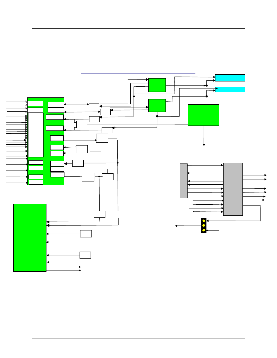
5. Platform Management
The server boards SE7320SP2 and SE7525GP2 have been designed to support the Intel
Onboard Platform Instrumentation level of management. Integrated onto the server board is a
National Semiconductor* PC87431 Mini-BMC (mBMC) which will support the functionality of the
Essentials level of management. These server boards do not support the Flexible Management
Connector which supports the optional Professional or Advanced Intel management modules.
Figure 13 - Block Diagram of Platform Managment Architecture
FMC_CPU1_SKTOCC_N
CPU1 VRD OUTEN &
System PWRGD Logic
FMC_CPU2_SKTOCC_N
CPU2 VRD OUTEN Logic
GPIO40
SUS_STAT_N
6300ESB
RTCRST_N
SPEAKER
SPKR
GPIO48
CPU1
CPU2
8742X SIO
Chassis
FANIN6
FANIN5
Security
CPU1_PROCHOT_N
CPU2_PROCHOT_N
P1_Prochot_N
P2_Prochot_N
P1_Thermtrip_N
P2_Thermtrip_N
HECETA 7
Tach1
Tach2
PWM1
PWM2
FET
AMP
CPU1 Thermal Diode
CPU2Thermal Diode
P1_VID[5:0]
P2_VID[5:0]
+12V1
+12V2
+12V3
FSB_Vtt
Chipset_Core
ICH_Core
CPU1_Vccp
CPU2_Vccp
3.3V
+5V
SCSI_Core
Mem_Core
Mem_Vtt
GBIT _Core
-12V
+3.3 S/B Vcc
SCSI_term1
SCSI_term2
RTD (1)
RTD (2)
P12V_SCALED
P_VTT
P5V
P12V_CPU_SCALED
DDR Core
DDR Vtt
Gb LAN Core
VID_CPU0[5:0]
VID_CPU1[5:0]
P3V3_STBY
P1V5
P3V3
P_VCCP0
P_VCCP1
P1V8_SCSI
N12V_SCALED
FET
AMP
FAN
Zone2
Zone 1
GTL to 3.3V
translation
Logic
GTL to 3.3V
translation
Logic
GTL to 3.3V
translation
Logic
Not Used
Not Used
SCSIB_TERMPWR
SCSIA_TERMPWR
GTL to 3.3V
translation
Logic
Tach3
Tach4
FAN
SECURE_MODE_KB
CHASSIS INTRUSION
Temp
CPU 1 IERR
CPU 2 IERR
GPI6
GPI7
Mem
FAN
Fan
Fan
LED
PWR_LED
CPU
FAN
CPU
FAN
SECURE_MODE_KB
FP_ID_BTN_N
Front Panel
Connector
FP_ID_LED_N
FP_SYS_FLT_LED_A
FP_PWR_BTN
FP_RST_BTN
ICH_PWR_BTN
ICH_RST_BTN
FP_NMI_BTN
SYS_NMI
CPU2_SEL
CPU1_SEL
CPU_CFG_ERR_N
GP1
GP2
GP3
GP4
GP5
LED1
LED2
RSTout
PWBout
NMI
PWBin
RSTin
mBMC
GP6
GP7
GP8
PWRGD
FRB3_TMR_HALT_N
PS_PWR_GD
LEDC1
FP_SYS_FLT_LED_C
LEDC2
SYS_SMI
SMI
GND
AND
Thermtrip
FANIN1
FANIN3