ICP DAS USA MSM-6226 User Manual
Page 19
Publication date: March., 2011
Revision A1
7
•
••
•
LED Indicators
LED
Color
Function
System LED
CPURUN
Green
Lit when CPU is on and good
POWER
Green
Lit when AC power is on and good
ACT
Green
Lit when LEDSET set on active mode
FDX
Green
Lit when LEDSET set on full-duplex mode
SPD
Green
Lit when LEDSET set on speed mode
10/100Mbps Ethernet TP Port 1 to 24 LED
LNK
Green
Lit when connection with remote device is good
Off when cable connection is not good
ACT/FDX/ SPD
Amber
(TP Port 1 to
24 LED)
a. LEDSET set on ACT (active) mode:
Blinks when any traffic is present
b. LEDSET set on FDX (full-duplex) mode:
Lit when full-duplex mode is active
Blinks when any collision is present
c. LEDSET set on SPD (speed) mode:
Lit when 100Mbps speed is active
Off when 10Mbps speed is active
10/100/1000Mbps Gigabit TP/Fiber Port 25, 26 LED
LNK
Green
Lit when connection with remote device is good
Off when cable connection is not good
FB
Green
Lit when Fiber port is active
Off when TP port is active
ACT/FDX/ SPD
Green
(Port 25,
26 LED)
a. LEDSET set on ACT (active) mode:
Blinks when any traffic is present
b. LEDSET set on FDX (full-duplex) mode:
Lit when full-duplex mode is active
Blinks when any collision is present
c. LEDSET set on SPD (speed) mode:
Lit when 1000Mbps speed is active
Off when 10/100Mbps speed is active
Table1-1
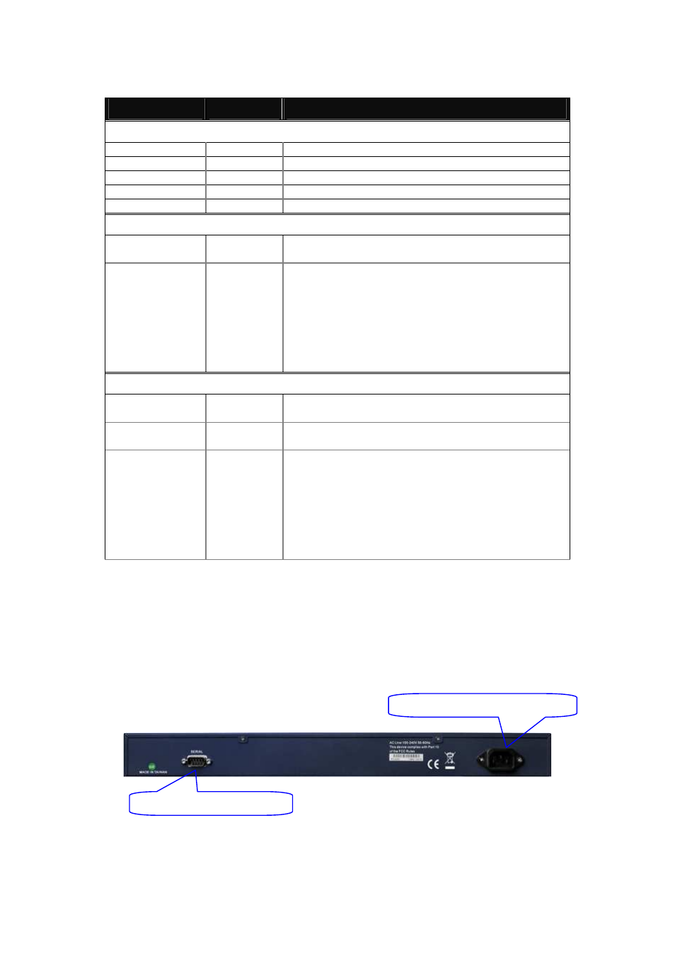
1-4-2. User Interfaces on the Rear Panel
One RS-232 DB-9 interface is offered for configuration or management. And
there is one AC power input socket for having the switch powered on or off.
Fig. 1-3 Rear View of MSM-6226/D
RS-232 DB-9 Connector
AC Line 100-240V 50/60 Hz