Sio routing, Figure 33. high-speed cmos termination, Figure 34. sio routing example – Intel CHIPSET 820E User Manual
Page 55
Intel
®
820E Chipset
R
Design Guide
55
Figure 33. High-Speed CMOS Termination
high_spd_cmos_term
MCH
RIMM_0
RIMM_1
91
Ω
Vterm
39
Ω
R1
R2
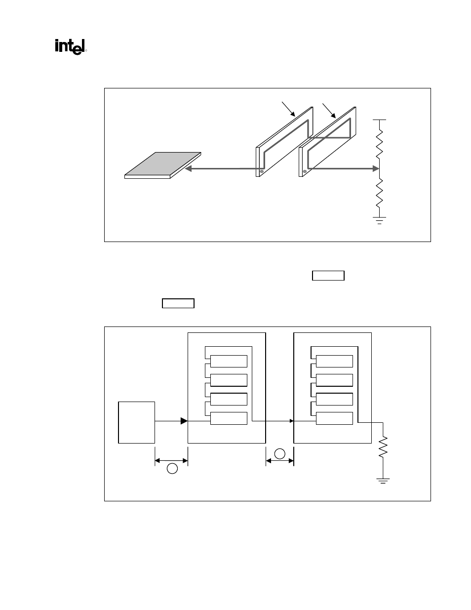
2.7.4.1. SIO
Routing
The SIO signal must be routed from RIMM to RIMM, as shown in Figure 34. The SIO signal requires a
2.2 k
Ω
to 10 k
Ω
terminating resistor on the SOUT pin of the last RIMM. SIO is routed with a standard
5 mil-wide, 60
Ω
trace. The motherboard routing lengths for the SIO signal are the same as those for
RSL signals. (See Figure 34.)
Figure 34. SIO Routing Example
A
B
0" - 3.50"
0.4" - 0.45"
SIN B36
SIN B36
A36 SOUT
A36 SOUT
2.2K
Ω
-
10K
Ω
sio_route.vsd
82820
MCH
N
3
2
1
N
3
2
1