Table 46. lan connect i/f – Intel CHIPSET 820E User Manual
Page 135
Intel
®
820E Chipset
R
Design Guide
135
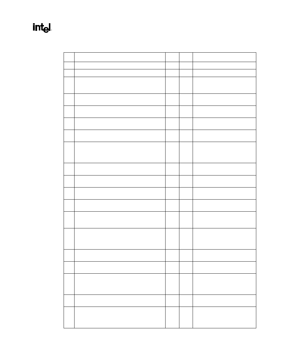
Table 46. LAN Connect I/F
# Layout
Recommendations Yes
No Comments
1
Stack-up: 5 mils wide, 10 mil spacing
2 Z
0
= 60
Ω
± 15%
Signal integrity requirement
3
LAN max. trace length, ICH2 to CNR :
L = 3 inches to 9 inches (0.5 inch to 3 inches on
card)
To
meet
timing
requirements
4
Stubs due to R-pak CNR/LOM stuffing option
should not be present.
To
minimize
inductance
5
Max. trace lengths, ICH2 to 82562EH/ET/EM :
L = 4.5 inches to 8.5 inches
To
meet
timing
requirements
6
Max. mismatch between length of a clock trace and
length of any data trace is 0.5 inch.
To meet timing and signal quality
requirements
7
Maintain constant symmetry and spacing between
the traces within a differential pair.
To meet timing and signal quality
requirements
8
Keep the total length of each differential pair less
than 4 inches.
Issues found with traces longer
than 4 inches: IEEE phy
conformance failures, excessive
EMI and/or degraded receive BER
9
Do not route the transmit differential traces within
70 mils of the receive differential traces.
To
minimize
crosstalk
10
Distance between differential traces and any other
signal line is 70 mils.
To
minimize
crosstalk
11
Keep max. separation between differential pairs at
7 mils.
To meet timing and signal quality
requirements
12
Differential trace impedance should be controlled to
~100 Ω.
To meet timing and signal quality
requirements
13
For high speed signals, the number of corners and
vias should be minimized. If a 90º bend is required,
it is advisable to use two 45º bends.
To meet timing and signal quality
requirements
14
Traces should be routed away from board edges by
a distance greater than the trace height above the
ground plane.
This allows the field around the
trace to couple more easily to the
ground plane, rather than to
adjacent wires or boards.
15
Do not route traces and vias under crystals or
oscillators.
This will prevent coupling to or
from the clock.
16
Ration of trace width to height above the ground
plane should be between 1:1 and 3:1.
To control trace EMI radiation
17
Traces between decoupling and I/O filter capacitors
should be as short and wide as practical.
Long and thin lines are more
inductive and would reduce the
intended effect of decoupling
capacitors.
18
Vias to decoupling capacitors should have sufficient
diameter.
To
decrease
series
inductance
19
Avoid routing high-speed LAN or phone line traces
near other high-frequency signals associated with a
video controller, cache controller, CPU or similar
devices.
To
minimize
crosstalk