Ich2 – lan interconnect guidelines, Figure 64. ich2 / lan connect section, Table 22. lan design guide section reference – Intel CHIPSET 820E User Manual
Page 103
Intel
®
820E Chipset
R
Design Guide
103
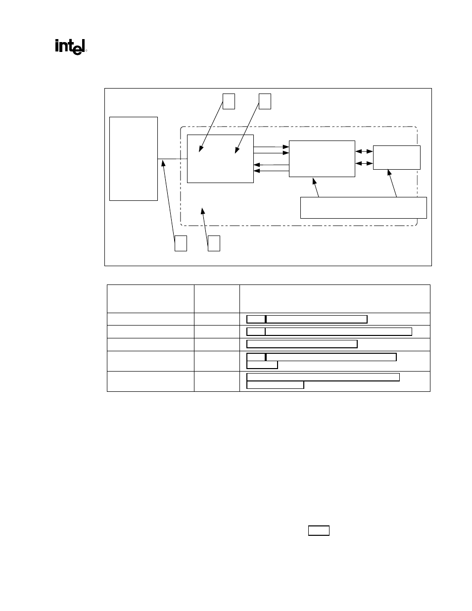
Figure 64. ICH2 / LAN Connect Section
ICH2_LAN_connect
Dual footprint
Intel
®
82562EH/82562ET
ICH2
Magnetics
module
Connector
A
B
D
C
Refer to Intel
82562EH/82562ET section
Table 22. LAN Design Guide Section Reference
Layout Section
Previous
Figure
Reference
Design Guide Section
ICH2 – LAN interconnect
A
2.22.1 ICH2 – LAN Interconnect Guidelines
General routing guidelines
B,C,D
2.22.2 General LAN Routing Guidelines and Considerations
Intel
®
82562EH
B
Intel
®
82562ET/82562EM
C
2.22.4 Intel® 82562ET / Intel® 82562EM Component
Guidelines
Dual-footprint layout
D
2.22.1.
ICH2 – LAN Interconnect Guidelines
This section contains guidelines for the design of motherboards and riser cards that comply with LAN
connect. The guidelines should not be treated as a specification, and the system designer must ensure, via
simulations or other techniques, that the system meets the specified timings. Special care must be taken
when matching the LAN_CLK traces to those of the other signals, as discussed next. The following are
guidelines for the ICH2-to-LAN component interface. The following signal lines are used on this
interface: LAN_CLK, LAN_RSTSYNC, LAN_RXD[2:0], and LAN_TXD[2:0].
This interface supports both Intel
82562EH and Intel
82562ET/82562EM components. Signal lines
LAN_CLK, LAN_RSTSYNC, LAN_RXD[0], and LAN_TXD[0] are shared by both components. Signal
lines LAN_RXD[2:1] and LAN_TXD[2:1] are not connected when the Intel
82562EH component is
installed. The AC characteristics of this interface are discussed in the Intel
®
82801BA I/O Controller
(ICH2) Datasheet. Dual footprint guidelines are found in Section 2.22.6.