Recommended stack-up, Inner-layer routing, Table 61. 28 – Intel CHIPSET 820E User Manual
Page 179: Stack-up examples
Intel
®
820E Chipset
R
Design Guide
179
5.1.4. Recommended
Stack-Up
Though numerous stack-up variations are possible, the following starting point is recommended:
W = 18 mils, H = 4.5 mils, T = 2.0, 1-ply 2116 prepreg
For other possibilities see the following table and the following figures:
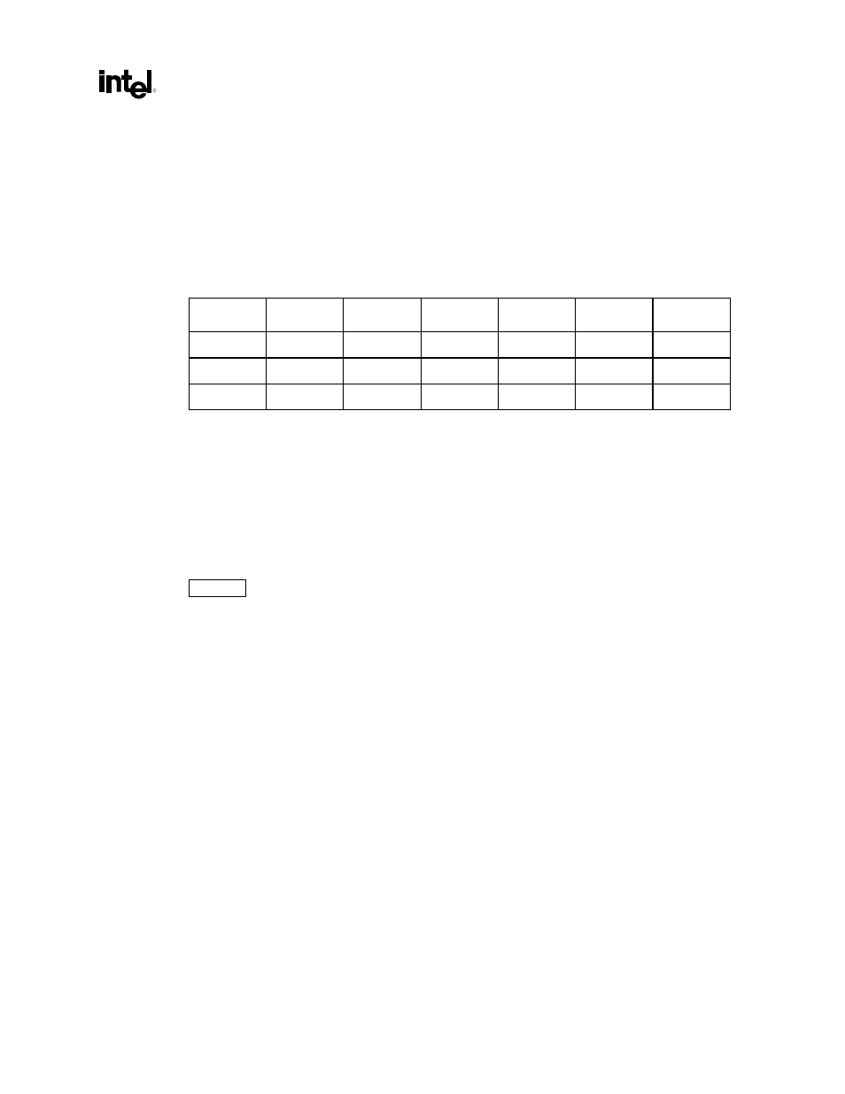
Table 61. 28
Ω
Ω
Ω
Ω
Stack-Up Examples
Sample
Zo
H
W
T
SM (max.)
Resin %
1 27.1 4.3 18.0 2.1 0.6 53.0
2 28.1 3.8 18.5 1.6 1.2 72.0
3 28.6 4.8 19.0 2.5 0.7 61.0
5.1.5. Inner-Layer
Routing
Inner-layer routing also has many possible stack-ups. For inner-layer routing, it is advisable to use the
following starting point:
W = 13.5 mils, H1 = 7 mils, H2 = 5, T = 1.2
If these parameters are used, the initial TDR should fall within the acceptable limit, 28
Ω
± 10%.
Figure 98 shows examples of both stripline and microstrip cross sections.