Figure 78. decoupling capacitor layout – Intel CHIPSET 820E User Manual
Page 123
Intel
®
820E Chipset
R
Design Guide
123
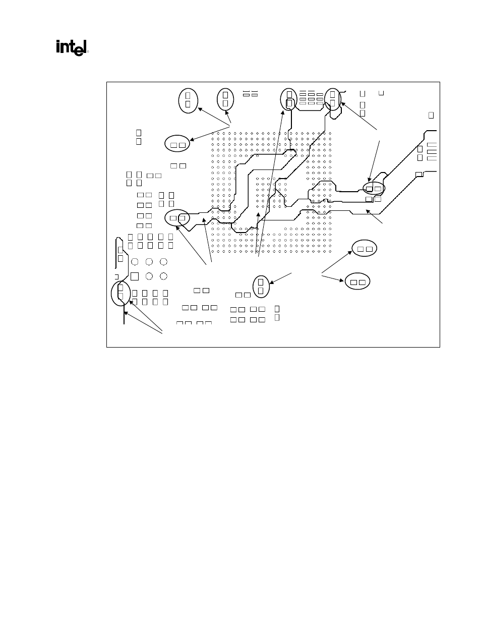
Figure 78. Decoupling Capacitor Layout
3.3 V Core
1.8 V Core
1.8 V Standby
3.3 V Standby
3.3 V Core
1.8 V Standby
5 V Ref
ICH2_decoupling_cap
The previous figure shows the layout of the ICH2 decoupling capacitors for various power planes around
the ICH2. The decoupling caps are circled, with an arrow pointing to the power plane/trace to which they
are connected.
See also other documents in the category Intel Computers:
- System Board G4H875-N (124 pages)
- LV22N Series (97 pages)
- Pentium 4 Processor Motherboard GA-8I865GME (72 pages)
- NETWORK PROCESSOR IXP2800 (430 pages)
- S5500WB (9 pages)
- System Board G4H875-C (129 pages)
- TIGI2U (26 pages)
- SE8500HW4 (132 pages)
- ISP1100 (81 pages)
- C50277-001 (73 pages)
- ESM-2740 (93 pages)
- SR6850HW4 (119 pages)
- SC5600 (24 pages)
- DP45SG (86 pages)
- SERVER SYSTEM SR2500AL (210 pages)
- GA-N680SLI-DQ6 (112 pages)
- SOCKET 370 CELERON TS-ASP3 (61 pages)
- NetStructure MPCBL0001 (198 pages)
- SROMBSASMR (AXXROMBSASMR) (40 pages)
- Express 5800 TM700 (132 pages)
- SE7520BD2 (64 pages)
- SR9000MK4U (258 pages)
- GS-SR195V (56 pages)
- OCPRF100 MP (149 pages)
- MINI-ITX BOARD AR-B1890 (44 pages)
- SDS2 (145 pages)
- SE7520BD2-D2 (27 pages)
- SC5650 (22 pages)
- Board SE7520BB2 (17 pages)
- GS-SR168 (52 pages)
- Express 5800/120Ld (194 pages)
- 7400 (16 pages)
- PCM-3370 (128 pages)
- S5000XAL (113 pages)
- Integrated Touchscreen Computer J2 650 (78 pages)
- ECB-870 (115 pages)