MITSUBISHI ELECTRIC FR-S520 User Manual
Page 133
124
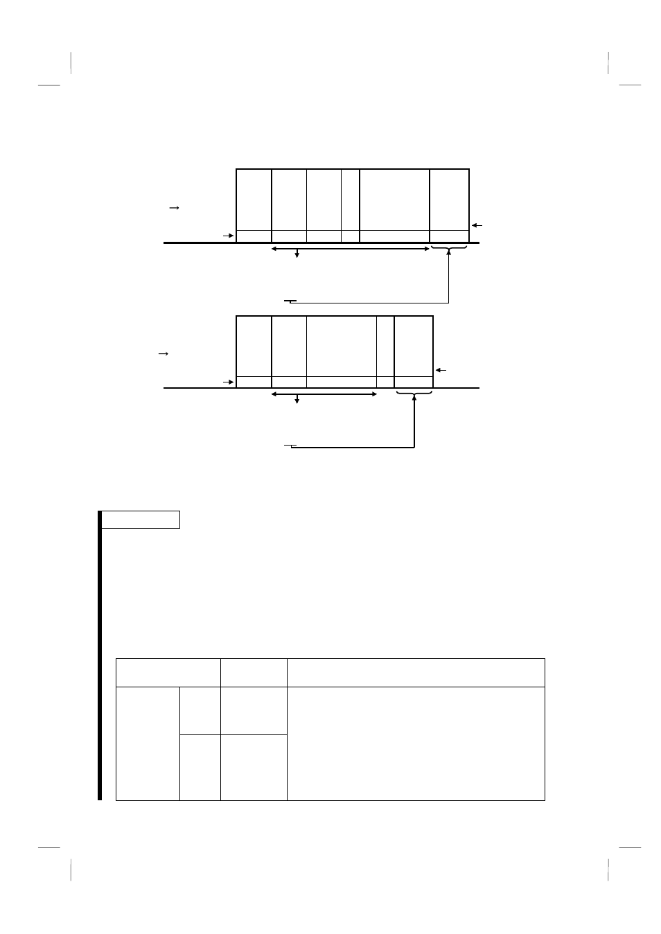
7) Sum check code
The sum check code is 2-digit ASCII (hexadecimal) representing the lower 1 byte
(8 bits) of the sum (binary) derived from the checked ASCII data.
E
N
Q
1
0
1
E
1
0
7
A D
F
4
H05
H30 H31
H31
H45 H31
H30 H37 H41 H44 H46 H34
S
T
X
0
1
1
7
0
3
0
H02
H30 H31
H37
H31 H37
H30 H03 H33 H30
E
T
X
7
Sum
check
code
Sum
check
code
Binary code
(Example 1)
Computer
Inverter
ASCII code
(Example 2)
Inverter
Computer
ASCII code
Binary code
H
1F4
=
H
30
H
31
H
45
H
31
H
31
H
30
H
37
H
41
H
44
+
+
+
+
+
+
+
+
H
130
=
H
30
H
31
H
31
H
37
H
37
H
30
+
+
+
+
+
Sum
Sum
St
at
io
n
n
u
mber
Read time
St
at
io
n
n
u
mber
Data
Wait
ing
ti
m
e
In
st
ru
cti
o
n
co
de
8) Error code
If any error is found in the data received by the inverter, its definition is sent back to
the computer together with the NAK code. (Refer to page 128.)
REMARKS
1. When the data from the computer has an error, the inverter will not accept that
data.
2. Any data communication, e.g. run command, monitoring, is started when the
computer gives a communication request. Without the computer's command, the
inverter does not return any data. For monitoring, therefore, design the program
to cause the computer to provide a data read request as required.
3. When accessing the parameter settings, data for link parameter expansion
setting differs between the parameters as indicated below:
Instruction
Code
Data
Read
H7F
Link
parameter
expansion
setting
Write
HFF
H00: Pr. 0 to Pr. 99 can be accessed.
H01: Calibration parameters C1 to C7 (Pr. 900 to
Pr. 905) and communication parameter n13
(Pr. 145) can be accessed.
H03: Communication parameters n1 to n12
(Pr. 331 to Pr. 342) can be accessed.
H09: Communication parameters n14 to n17
(Pr. 990 to Pr. 993) can be accessed.