4 dr-scan sequence, 3 communication through tap, 13 .2 .4 dr-scan sequence -5 – Maxim Integrated MAXQ622 User Manual
Page 192: 13 .3 communication through tap -5, Figure 13-2 . tap and tap controller -5
MAXQ612/MAXQ622 User’s Guide
Maxim Integrated
13-5
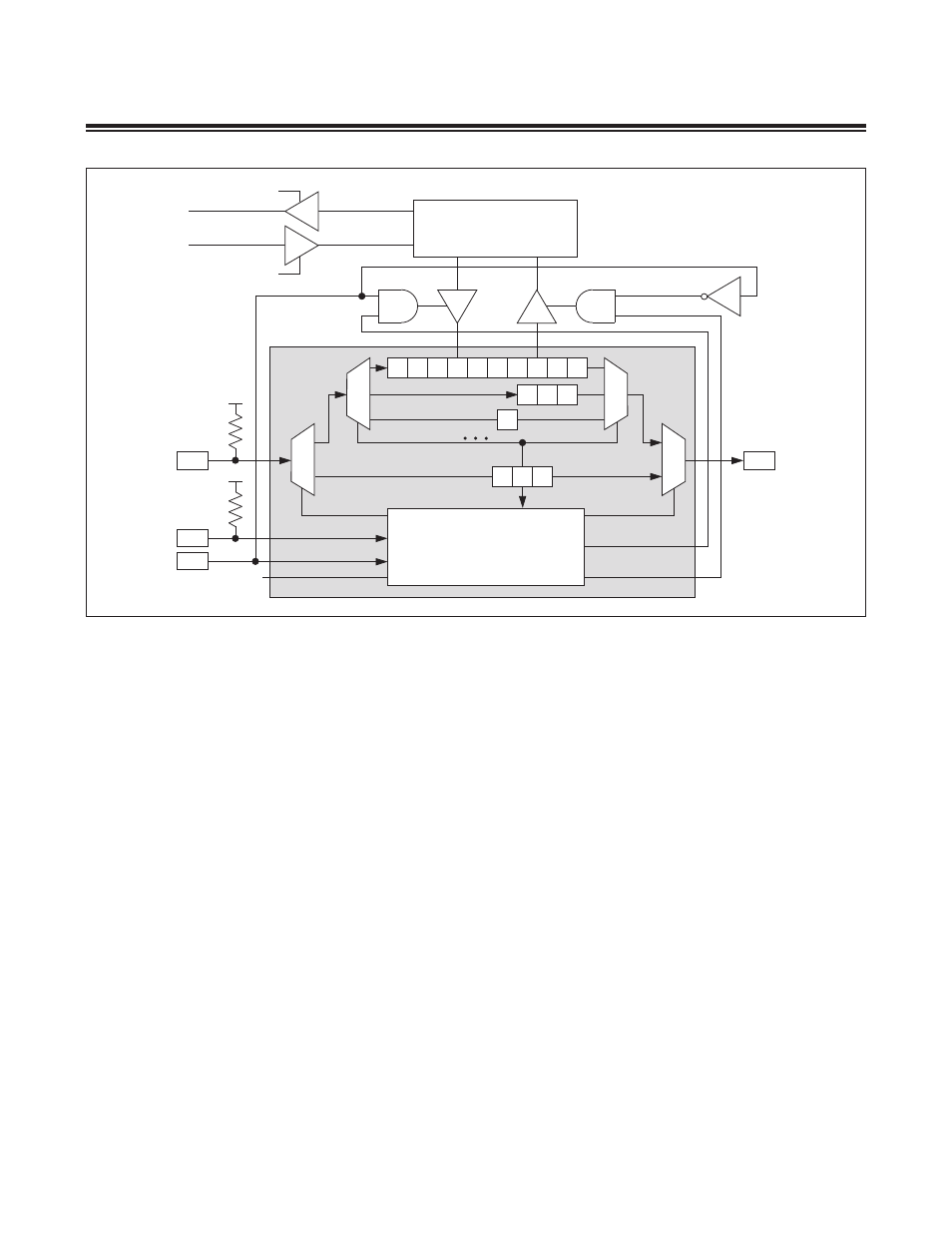
Instruction register (IR[2:0]) settings other than those listed and described above are reserved for internal use . As can
be seen in Figure 13-2, the instruction register serves to select the length of the serial data register between TDI and
TDO during the shift-DR state .
13.2.4 DR-Scan Sequence
Once the instruction register has been configured to a desired state (mode), transactions are performed via a data
buffer register associated with that mode . These data transactions are executed serially in a manner analogous to the
process used to load the instruction register and are grouped in the TAP controller state sequence starting from the
select-DR-scan state . In the TAP controller state sequence, the shift-DR state allows internal data to be shifted out
through the TDO pin, while the external data is shifted in simultaneously through the TDI pin . Once a complete data pat-
tern is shifted in, input data can be latched into the parallel buffer of the selected register on the falling edge of TCK in
the update-DR state . On the same TCK falling edge, in the update-DR state, the internal parallel buffer is loaded to the
data shift register for output . This shift-DR/update-DR process serves as the basis for passing information between the
external host and the MAXQ612/MAXQ622 microcontrollers . These data register transactions occur in the data register
portion of the TAP controller state sequence diagram and have no effect on the instruction register .
13.3 Communication Through TAP
The TAP controller is in test-logic-reset state after a power-on-reset . During this initial state, the instruction register
contains bypass instruction and the serial path defined between the TDI and TDO pins for the shift-DR state is the 1-bit
bypass register . All TAP signals (TCK, TMS, TDI, and TDO) default to being weakly pulled high internally on any reset .
The TAP controller remains in the test-logic-reset state as long as TMS is held high . The TCK and TMS signals can be
manipulated by the host to transition to other TAP states . The TAP controller remains in a given state whenever TCK
is held low .
Figure 13-2. TAP and TAP Controller
TDO
TDI
WRITE
TCK
DEBUG
UPDATE-DR
UPDATE-DR
V
DD
TAP CONTROLLER
TMS
SYSTEM PROGRAM
READ
POWER-ON
RESET
BYPASS
INSTRUCTION REGISTER
7
6
5
4
3
2
1
0 s1 s0
2
1
0
2
1
0
V
DD