Figure 11-2 . i, C master-transmitter data transfer -3, Figure 11-3 . i – Maxim Integrated MAXQ622 User Manual
Page 158: C master-transmitter and master-receiver -3
MAXQ612/MAXQ622 User’s Guide
Maxim Integrated
11-3
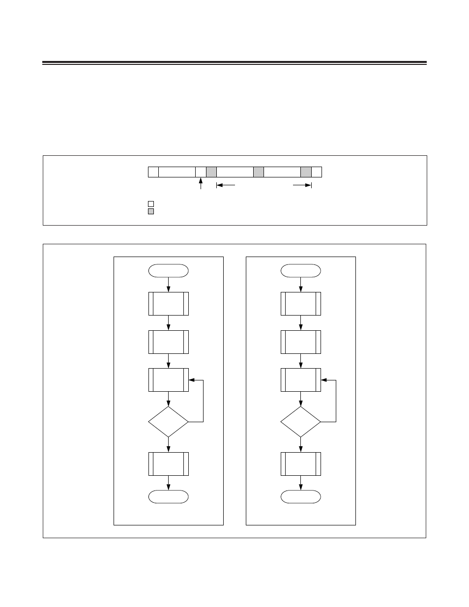
flag is set (I2CTXI = 1) . The I2CTXI flag is set after the acknowledge bit has been received from the slave . This gener-
ates an interrupt to the CPU if the transmit interrupt is enabled (I2CTXIE = 1) . On receiving acknowledgement (ACK)
from the slave, the master can then start transmitting data bytes to the slave . The master refrains from generating the
SCL clock until data has been written to I2CBUF . The I
2
C controller starts generating the SCL clock only after the
I2CBUF has been written to and the necessary SCL low time requirement has been satisfied . There is no limit as to the
number of bytes to be transmitted . The master concludes the transfer by generating the STOP condition (I2CSTOP = 1)
and releasing the I
2
C signals .
Figure 11-2. I
2
C Master-Transmitter Data Transfer
Figure 11-3. I
2
C Master-Transmitter and Master-Receiver
S
DATA
0
SLAVE ADDR
A
P
A
DATA
A
WRITE
MASTER TO SLAVE
SLAVE TO MASTER
DATA TRANSFERRED
(n BYTES + ACKNOWLEDGE)
BEGIN
END
(A) MASTER TRANSMITTER
GENERATE
START
TRANSMIT
DATA
ANY MORE?
Y
N
GENERATE
STOP
TRANSMIT
SLAVE
ADDRESS
BEGIN
END
(B) MASTER RECEIVER
GENERATE
START
RECEIVE
DATA
ANY MORE?
Y
N
GENERATE
STOP
TRANSMIT
SLAVE
ADDRESS