3 i2c controller reset, 11 .3 i, C controller reset -7 – Maxim Integrated MAXQ622 User Manual
Page 162: Table 11-2 . sample i, C clock setting for 50ns rise/fall time -7, C controller reset, Table 11-2. sample i, C clock setting for 50ns rise/fall time
MAXQ612/MAXQ622 User’s Guide
Maxim Integrated
11-7
Similarly, if an external master pulls SCL low before the I
2
C controller has finished counting its I2CCKH cycles, the I
2
C
controller starts counting its I2CCKL cycles and releases SCL once the I2CCKL count has expired .
Theoretically, the I
2
C bit rate is limited to f
SYS
/8 in both master mode and slave mode . Practically, the I
2
C specification
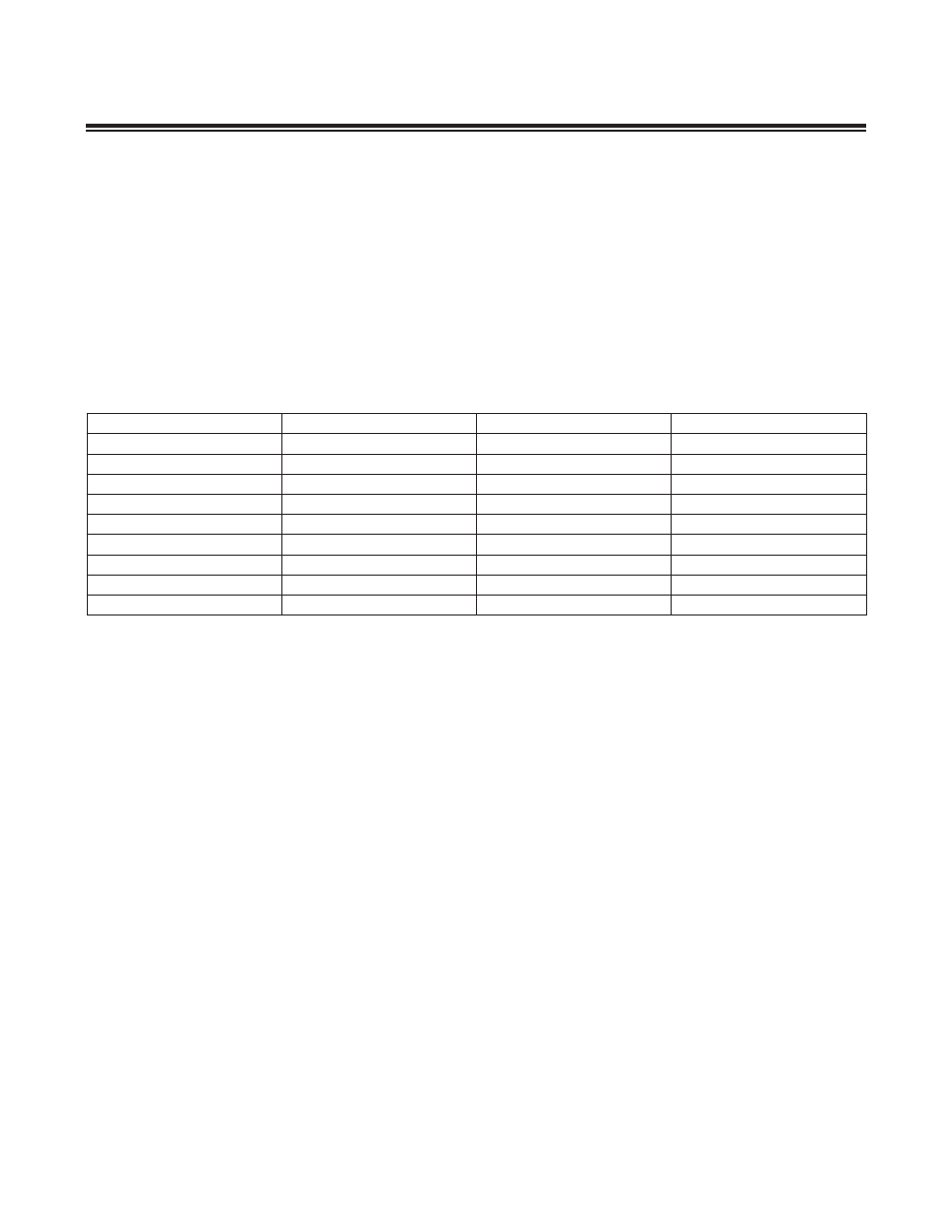
requires minimum timing on SCL high and low periods . Therefore, the application should set the I2CCK register so
the I
2
C timing requirement is satisfied . Table 11-2 shows how the application can configure the I2CCKH and I2CCKL
registers .
I2CCKH = Number of System Clock Required - 1
I2CCKL = Number of System Clock Required - 1
Note that the I
2
C Bit Rate is limited by the minimum SCL high and low time and is not limited to the implementation .
If the requirement for minimum high and low time is removed, the module can operate up to 1/8 system clock rate .
11.3 I
2
C Controller Reset
In the case where the MAXQ controller would like to terminate an on-going I
2
C communication, it can set the I
2
C reset
bit (I2CRST) in the I2CCN register . The I2CRST bit is set to 1 by software and can only be cleared to 0 by hardware .
By setting the I2CRST bit to 1, the I
2
C controller initiates the abort process . If a transfer is not in progress (I2CBUSY = 0)
and the I
2
C controller is acting as a master, it generates a STOP condition immediately . Similarly, if a transfer is not in
progress and the I
2
C controller is acting as a slave, it releases SDA and returns to the idle state .
If a transfer is in progress (I2CBUSY = 1), when acting as a master-transmitter, setting this bit generates a STOP condi-
tion at the next SCL low time . In master-receiver mode, since the SDA line is actively being driven by the slave during
the byte transfer, the master NACKs the current byte and generates a STOP conditon after the ACK bit . In both cases,
the timeout timer starts when the I
2
C controller tries to initiate a STOP condition if enabled . If the timeout timer expires
before the STOP condition can be generated, a timeout interrupt is generated to the CPU if enabled . The I2CRST bit
is also cleared to 0 by the timeout event .
In slave mode, the I
2
C controller releases the SDA line on the next SCL low period . While the reset is in progress, the
I2CBUSY bit is set to 1 and writes to I2CEN are permitted . The I2CACK bit is set to 1 by hardware and any write to this
bit is ignored until I2CRST = 0 . The I2CACK bit is set to 1 to force a NACK condition in receive mode . On completion
of the abort, the I2CRST bit automatically is self-cleared to 0 . At the conclusion of the I
2
C reset operation, the I2CBUF
register and I2CSTART and I2CSTOP bits are reset to 0 . In addition, all the flags in the I2CST register, with the excep-
tion of I2CTOI, I2CSCL, and I2CSPI, are also reset to 0 . The I2CRST bit is also reset to 0 when I2CEN = 0 .
Table 11-2. Sample I
2
C Clock Setting for 50ns Rise/Fall Time
f
SYS
(MHz)
I2CCKH
I2CCKL
FREQUENCY (ksps)
20
7
11
1000
20
17
31
400
20
92
106
100
12
3
7
1000
12
9
19
400
12
55
63
100
8
2
4
1000
8
6
12
400
8
36
42
100