Operator’s manual – Great Plains DICKEY-john MVT Monitor Operator User Manual
Page 81
OPERATOR’S MANUAL
IntelliAg MVT
11001-1643-201401
72 / ACCESSORY SENSORS
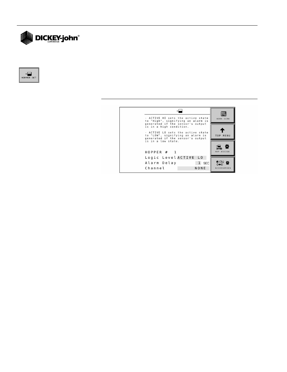
To Set the Active State and Alarms of Hopper Sensors:
The Hopper Set screen controls the active state of the hopper sensor as
well as the alarm delay time.
1. At the Hopper Assignment screen, press the Hopper Set button.
2. Use the rotary dial to highlight the yellow input box.
3. Push in the rotary dial to select or enter a value.
4. Push in the rotary dial to accept.
Figure 61
Hopper Set Screen
LOGIC LEVEL
Logic Level sets the active state of the sensor and allows flexibility to
connect sensors that have different active outputs. There are two settings
available:
NOTE:
For a Dj Hopper Level sensor,
this value should be set to
ACTIVE LO.
ACTIVE HIGH
•
Sets the active state to “High” signifying that an alarm is generated if
the sensor’s output is in a high state. Use this setting if the connected
sensor outputs a high condition when active.
ACTIVE LO
•
Sets the active state to “Low” signifying that an alarm is generated if
the sensor’s output is in a low state. Use this setting if the connected
sensor outputs a low condition when active.
ALARM DELAY
Alarm Delay controls the delay time between the detection of a hopper
alarm condition and the generation of the resulting alarm. The value is
entered in seconds.
CHANNEL
Assigns the hopper sensor to a specific control channel.