Operator’s manual, Planter control module (pcm), Working set member (wsmb) module (optional) – Great Plains DICKEY-john MVT Monitor Operator User Manual
Page 13
OPERATOR’S MANUAL
IntelliAg MVT
11001-1643-201401
4 / SYSTEM COMPONENTS
PLANTER CONTROL MODULE (PCM)
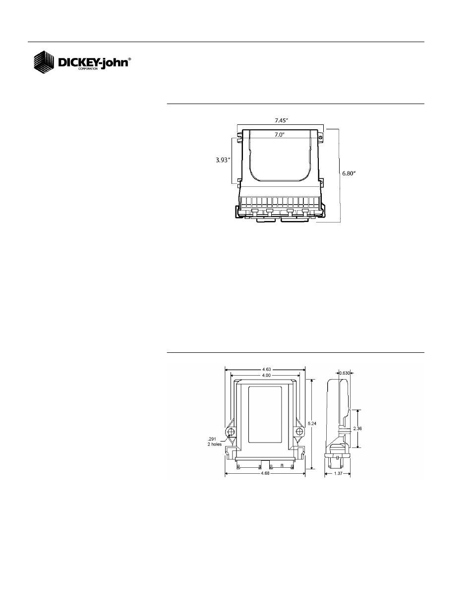
Figure 2
Planter Control Module
The Planter Control module houses the system’s primary interface device.
All system parameters, constants, and memory are stored in the PCM. The
PCM has two channels for planter control. In addition, the PCM can accept
inputs from 8 accessory sensors: 3 hopper level, 3 air pressure, 2 RPM, 1
ground speed, and up to 12 population/blockage sensors. The PCM module
uses a 48-pin connector with a jackscrew to secure the connector to the
module. The PCM is typically mounted on the implement.
WORKING SET MEMBER (WSMB) MODULE
(OPTIONAL)
Figure 3
Working Set Member Module
Each Working Set Member (WSMB) module is an auxiliary to the Planter
Control Module (PCM). Each WSMB can accept up to 18 rows of seed
sensors. The WSMB passes information directly to the PCM. Up to 5
WSMB’s can be installed to monitor up to 84 rows. The flexible design of
the WSMB allows for installation virtually anywhere on the implement.