Operator’s manual, Pressure sensor setup – Great Plains DICKEY-john MVT Monitor Operator User Manual
Page 77
OPERATOR’S MANUAL
IntelliAg MVT
11001-1643-201401
68 / ACCESSORY SENSORS
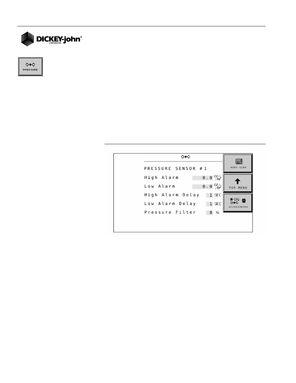
PRESSURE SENSOR SETUP
The Pressure Sensor Setup screen controls the parameters for each
pressure sensor including:
•
High alarm
•
Low alarm
•
High alarm delay
•
Low alarm delay
•
Pressure filter
To Setup Pressure Sensors:
1. At the Accessories screen, press the Pressure button.
2. Highlight the yellow input box and push in the rotary dial to open
keypad and set the desired values.
3. Press the OK button and push in rotary dial to accept.
Figure 58
Pressure Setup Screen
NOTE:
The Auto Config button detects
the presence of a pressure
sensor and automatically
configures and populates into
the Accessories screen.
HIGH/LOW ALARM
Sets the pressure value at which a high or low pressure warning error is
generated. The value is entered in seconds
.
HIGH ALARM/LOW ALARM DELAY
Establishes the delay between the detection of a high or low pressure alarm
condition and the resulting alarm display. The value is entered in seconds.
PRESSURE FILTER
Filters the signal out of the pressure sensor. Typically no filtering is required
and therefore the standard value is set at 0%. If the pressure readout on the
Main Word screen is oscillating in excess of 10%, increasing the filter value
filters the signal to reduce the oscillation. For a true pressure value this
number should be set to 0%.