Removing the bail sensor – HP 220 User Manual
Page 119
1 Remove the electronicsĆenclosure
cover D page 6Ć5.
2 Remove the window D page 6Ć15.
3 Remove the center cover D page 6Ć16.
4 Remove the right endcover D page 6Ć19.
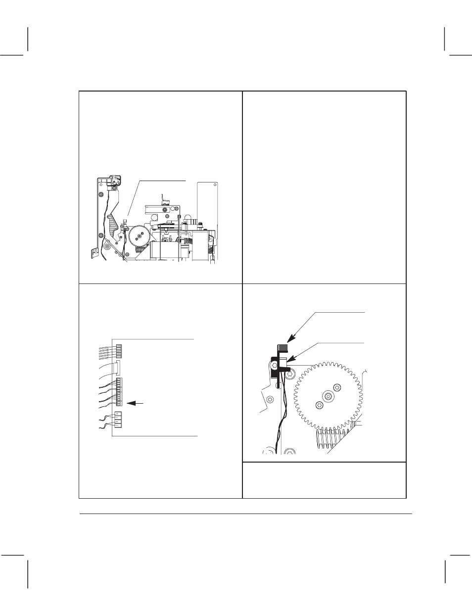
Bail-sensor
connector
Bail sensor
5 Note the position of the bailĆsensor cable
for reassembly. Incorrect positioning
could cause obstruction of the cartridge
carriage and motor gears.
6 Disconnect the bailĆsensor cable
connector from the main PCA, and from
its ferrite and holding clip on the right
sideplate.
7 Carefully feed the bailĆsensor cable out
from the electronics enclosure and from
under the motor assemblies.
8 Unclip the bail sensor from its holder,
and lift it, with cable, clear of the plotter.
Calibration: After having
reassembled the plotter, perform
the bail calibration D chapter 7.
The ferrite holder opens from the top.
Reassembling: The cable goes through
the same ferrite as for the windowĆsensor
cable D page 6Ć24.
Bail sensor
Bail-sensor
holder
6Ć55
Removal and Replacement
C3187Ć90000
Removing the Bail Sensor