Warning, C. high altitude installations – Heat & Glo Fireplace XLR-PLUS-PB-AU User Manual
Page 43
43
Heat & Glo • XLR-PLUS-N-AU, XLR-PLUS-PB-AU • 2264-900 Rev. o • 1/13
CHECK FOR GAS LEAKS
Explosion Risk
Fire Risk
Asphyxiation Risk
• Check all fittings and connections.
• Do not use open flame.
• After the gas line installation is complete, all
connections must be tightened and checked
for leaks with a commercially-available, non-
corrosive leak check solution. Be sure to rinse
off all leak check solution following testing.
Fittings and connections may have loosened
during shipping and handling.
WARNING
Valve Pressure Taps
The pressure taps are available through the front of the
appliance. The decorative mesh front and fireplace gas
assembly must be removed to gain access to the pressure
taps.
C. High Altitude Installations
NOTICE: If the heating value of the gas has been reduced,
these rules do not apply. Check with your local gas utility
or authorities having jurisdiction.
When installing above 2000 ft. (610 m) elevation:
Reduce burner orifice 4% for each 1000 ft. (305 m) above
2000 (610 m).
Figure 11.2. Remove Valve Plate Screws
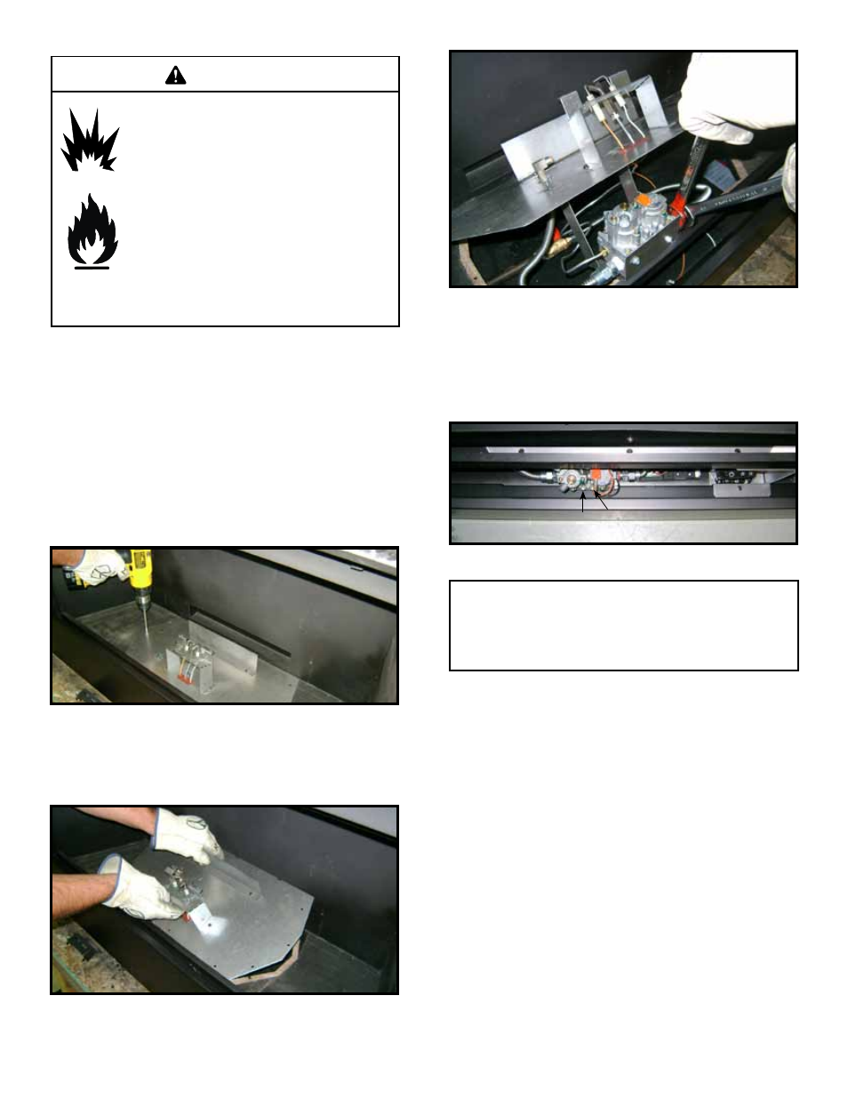
3. Set the valve bracket on the front lip of the firebox bot-
tom. Turn “off” the ball valve. Disconnect gas valve
from the gas flex ball valve assembly at the pressure
fitting. See Figure 11.4.
Figure 11.3. Remove Valve Plate
4. Lift the valve assembly up and out to make necessary
service or repair.
Figure 11.4. Disconnect Gas Valve
Access Through the Valve Assembly
The lower access cover panel is removable if finishing
material has not been previously installed.
Remove Media Tray, Burner Assembly, and Base pan.
To access components:
1. Remove eleven screws around perimeter of valve
plate and one on the valve bracket that secure valve
plate to the firebox bottom. See Figure 11.2.
2. Lift the valve plate from the back so that the gas valve
can clear the valve plate hole in the bottom the firebox.
See Figure 11.3.
INLET
MANIFOLD
OUTLET
Figure 11.5. Pressure Taps
Note: The manifold and inlet pressure tabs can be accessed
from the front of the fireplace, this requires the decorative
front and fixed glass assembly to be removed (see Figure
11.5). The manifold and inlet pressure tabs can also be ac-
cessed by removing the valve assembly (see Figure 11.4).