1 power switches, Figure 58 power switches - 10kva nx, Table 24 rotary switch configuration – Emerson Liebert NX 10-30kVA User Manual
Page 82: Power switches, Table 24, Rotary switch configuration
Operating Instructions
74
9.1.1 Power Switches
The UPS can be isolated by means of power switches, mounted inside the cabinet and accessible after
opening the front door.
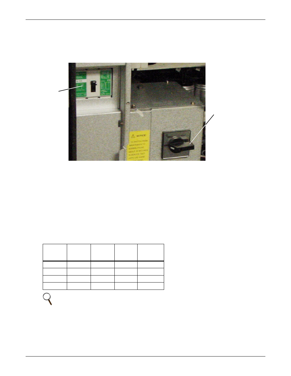
The location of the UPS power switches is shown in Figure 58.
Figure 58 Power switches - 10kVA NX
The UPS unit power switches are CB1 and SW1.
• CB1 - Input Isolator. Connects the utility supply to the UPS input.
• SW1 - Rotary switch. Has four positions—NORMAL, BYPASS, TEST and MAINT—that corre-
spond to different positions of the SW1-A/B/C/D.
The positions of the rotary switch (SW1) are:
• SW1-A - Output Isolator. Connects the output of the UPS to the load.
• SW1-B - Neutral Isolator. Connects neutral to the UPS.
• SW1-C - Bypass Isolator. Connects the UPS with the bypass supply.
• SW1-D - Maintenance Bypass Isolator. Permits supply of the load directly by the bypass
line for maintenance of the UPS unit.
The functions of the rotary switch are shown in Table 24.
Table 24
Rotary switch configuration
Rotary
switch
position
OUTPUT
(SW1-A)
BYPASS
(SW1-C)
MAINT
(SW1-D)
NEUTRAL
(SW1-B)
NORMAL
✔
✔
✔
BYPASS
✔
✔
✔
TEST
✔
✔
✔
MAINT
✔
NOTE
Do NOT turn the rotary switch too fast. Allow the rotary switch to stay in each position at least
three seconds before turning it to the next position.
SW1 - Rotary Switch
Inside the door, near
the center (above the
batteries)
CB1 - Utility
Connection
Inside the door,
left side