4 output dry contacts, Table 4 output dry contact relays, 5 epo input-optional – Emerson Liebert NX 10-30kVA User Manual
Page 25: Firmware before m200, Table 5 epo input contact relays, Output dry contacts, Epo input—optional, Table 4, Output dry contact relays, Table 5
Electrical Connections
17
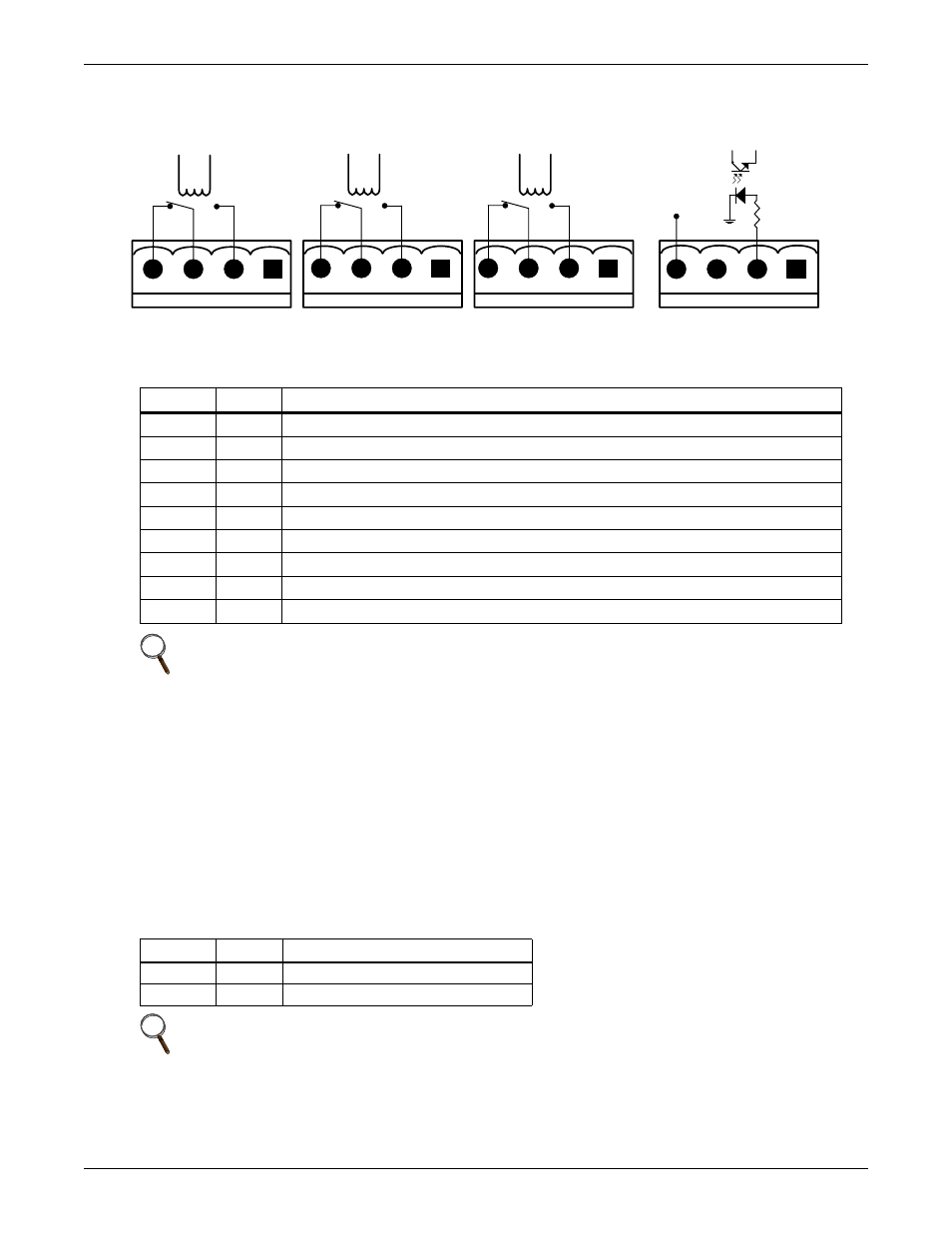
2.3.4 Output Dry Contacts
There are three output dry contact relays at the X1 slot (see Figure 10 and Table 4).
Figure 10 Output dry contacts and EPO wiring for firmware before M170
2.3.5 EPO Input—Optional
Firmware Before M200
The UPS has an Emergency Power Off (EPO) function that operates by a button on the control panel
or by a remote contact provided by the user. The EPO button is under a hinged, clear plastic shield.
The X2 slot, shown in Figure 10, is the remote EPO input interface. It is active when shorted from
EPO-L to EPO-H.
If an external Emergency Stop facility is required, it is connected terminals EPO-L to EPO-H of the
auxiliary terminal block (X2). It also is connected to the Normally Open remote stop switch between
these two terminals using shielded cable (see Figure 10 and Table 5). If this function is not used,
terminals EPO-L to EPO-H must be opened.
Table 4
Output dry contact relays
Position
Name
Description
J13.2
BFP_O
Bypass feedback protection relay. Normally open. Closed when bypass SCR is shorted.
J13.3
BFP_S
Bypass feedback protection relay center
J13.4
BFP_C
Bypass feedback protection relay. Normally closed. Open when bypass SCR is shorted.
J21.2
INV_O
Inverter mode relay. Normally open. Closed when UPS is in inverter mode.
J21.3
INV_S
Inverter mode relay center
J21.4
INV_C
Inverter mode relay. Normally closed. Open when UPS is in inverter mode.
J25.2
ACF_O
Main input fault relay. Normally open. Closed when main input is in fault.
J25.3
ACF_S
Main input fault relay center
J25.4
ACF_C
Main input fault relay. Normally closed. Open when main input is in fault.
NOTE
All auxiliary cables of terminal must be double-insulated. Wire should be 20-16AWG stranded
for maximum runs between 82 and 197 feet (25-60m), respectively.
Table 5
EPO input contact relays
Position
Name
Description
J28.2
EPO_L
Emergency Power Off Low
J28.4
EPO_H
Emergency Power Off High
NOTE
The Emergency Stop action within the UPS shuts down the rectifier, inverter and static
bypass. It does not internally disconnect the input power supply.
To disconnect ALL power to the UPS, open the upstream feeder breaker(s) when the remote
EPO is activated.
EPO-L
EPO-H
X2
X1
BFP_C
J21
J25
J28
BFP_S
BFP_O
INV_O
INV_S
INV_C
ACF_C
AC
F_S
ACF_O
+12V
J13