0 operation, 1 general description, 2 bypass supplies – Emerson Liebert NX 10-30kVA User Manual
Page 66: 3 operating modes, Peration, General description, Bypass supplies, Operating modes
Operation
58
7.0
O
PERATION
7.1
General Description
The standard NX consists of the UPS and internal batteries in a compact, single cabinet.
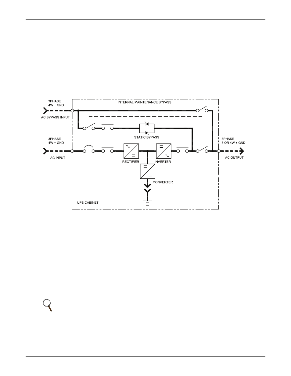
As shown in Figure 45, the AC utility source is input at CB1 and the rectifier converts the AC utility
into DC power. The inverter converts that DC power from the utility—or DC power from the batter-
ies—into AC power for the load. The batteries power the load through the inverter in the event of a
power failure. The utility source can also power the load through the static bypass.
If maintenance or repair of the UPS is necessary, the load can be switched without interruption in
service to the maintenance bypass.
Figure 45 Single module block diagram (dual input configuration)
7.2
Bypass Supplies
The circuit block labeled “Static Switch” and “Contactor” in Figure 45 contains an electronically con-
trolled switching circuit that enables the critical load to be connected to either the inverter output or
to a bypass power source via the static bypass line. During normal system operation the load is con-
nected to the inverter and the inverter contactor is closed; but in the event of a UPS overload or
inverter failure, the load is automatically transferred to the static bypass line.
To provide a clean (no-break) load transfer between the inverter output and static bypass line, the
static switch activates, connecting the load to bypass. To achieve this, the inverter output and bypass
supply must be fully synchronized during normal operating conditions. This is achieved through the
inverter control electronics, which make the inverter frequency track that of the static bypass supply,
provided that the bypass remains within an acceptable frequency window.
A manually controlled, maintenance bypass supply is incorporated into the UPS design. It enables the
critical load to be powered from the utility (bypass) supply while the UPS is shut down for routine
maintenance.
7.3
Operating Modes
The UPS is designed to operate as an on-line, double-conversion, reverse-transfer system in the fol-
lowing modes:
NOTE
When the UPS is operating in bypass mode or on maintenance bypass, the connected
equipment is not protected from power failures or surges and sags.