Figure 32 main components-typical unit, Ee figure 32 for – Emerson Liebert NX 10-30kVA User Manual
Page 53
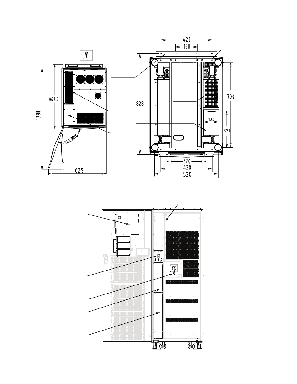
Installation Drawings
45
Figure 31 Dimensions continued—top and bottom views
Figure 32 Main components—typical unit
Rear stabiliz-
ing foot
Air Exhaust
Power Cable
Entry Area
Top and
Bottom
Air
10mm dia. threaded
mounting holes 4 (typ).
TOP VIEW
BOTTOM VIEW
Monitor
Board
(U2)
IntelliSlot
Communication
Ports
Input
Breaker
Input Breaker
Access Plate
Internal and
External Battery
Terminal Block
Access Plate
Battery
Trays
Power
Electronics
Parallel Board (M3)
Front View
(with door open)
DPN U3812048
Rev. 1
Rotary
System
Switch
See also other documents in the category Emerson Tools:
- 1000VA (2 pages)
- SAG581126000 (123 pages)
- Liebert NX 400V (132 pages)
- Nfinity 240V (44 pages)
- 10 kVA (16 pages)
- 12-20kVA (8 pages)
- NT5C06D (56 pages)
- Liebert Remote Monitoring Panel (28 pages)
- AccuVar UL94-5V (2 pages)
- PSA1000MT3-120U (2 pages)
- Liebert Power Solutions (44 pages)
- Series 610 (52 pages)
- Liebert GXT2-10KIPPCBL (2 pages)
- GXT2-PP20KRT208 (36 pages)
- Liebert FS 510 VDC (2 pages)
- Libert AC Power System (4 pages)
- 250-400kVA (72 pages)
- Albr BDS-40 (2 pages)
- NXL 400 kVA (2 pages)
- PSI-XR (4 pages)
- Liebert GXT2-10000RT208 (56 pages)
- LXP48F1 (43 pages)
- LIEBERT GXT5000R-208 (32 pages)
- 650VA (2 pages)
- Liebert NX 208V (80 pages)
- 480VAC (2 pages)
- Liebert NX 480V (108 pages)
- Liebert UPStation GXT2U (40 pages)
- 7400 (67 pages)
- GXT2U (40 pages)
- Series 600 (168 pages)
- Remote Power Monitor Panel (2 pages)
- Albr BDS-256XL (2 pages)
- Packaged Drives and Engineered Systems (24 pages)
- NXL UPS Systems (48 pages)
- LIEBERT NPOWER 30-130KVA (2 pages)