3 bypass mode, 4 maintenance mode, 5 locating the cabinet – Emerson Liebert NX 10-30kVA User Manual
Page 34: 6 cable installation, 1 wiring preparation, Removing the cover plates, Bypass mode, Maintenance mode, Locating the cabinet, Cable installation
Maintenance Bypass Cabinet
26
4.3
Bypass Mode
When the Maintenance Bypass Cabinet is in the Bypass mode, it provides an alternate path for power
to the connected equipment. Should the UPS need to be taken out of service for limited maintenance
or repair, manual activation of the bypass will cause an immediate transfer of the equipment from the
UPS inverter to the bypass source. In this mode, power will still be supplied to the UPS; however, the
load is NOT protected by the UPS.
4.4
Maintenance Mode
When the maintenance bypass cabinet is in the Maintenance mode, it provides an alternate path for
power to the connected equipment. Should the UPS need to be taken out of service for limited mainte-
nance or repair. In this mode of operation, no power is supplied to the UPS and the load is NOT pro-
tected by the UPS.
4.5
Locating the Cabinet
This Maintenance Bypass Cabinet may be mounted to the left of the UPS or installed as a stand-alone
unit. In either case, ensure that the unit is in a well-ventilated area and that there is clearance for
access to the switches and cable connections as required by national and local codes.
4.6
Cable Installation
4.6.1 Wiring Preparation
Be sure that the unit is not connected to any AC utility power source or UPS before installing any wir-
ing to this unit. This Maintenance Bypass Cabinet should be installed by a qualified / certified electri-
cian.
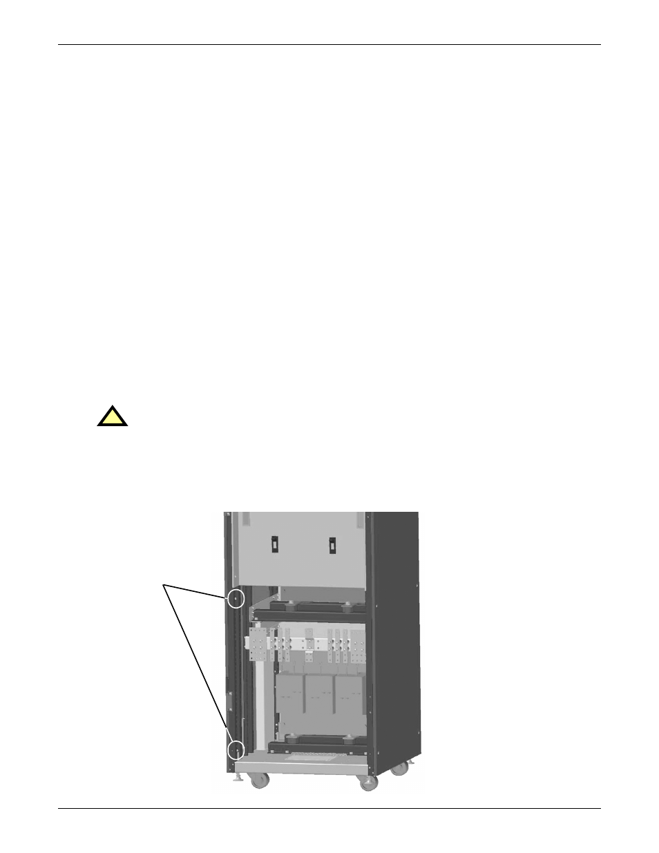
Removing the Cover Plates
Plates cover the input and output terminals on the front of the Maintenance Bypass Cabinet (see
Figure 18). Remove these and keep the screws and plates for reinstallation.
Figure 18 Maintenance Bypass Cabinet—access plate removed
!
WARNING
Please read this section thoroughly before attempting to install wiring to this unit.
Extract screws
from corners to
remove the
access plate