Figure 37 maintenance bypass interconnection, Table 12, Figure 37 – Emerson Liebert NX 10-30kVA User Manual
Page 58: Maintenance bypass interconnection
Installation Drawings
50
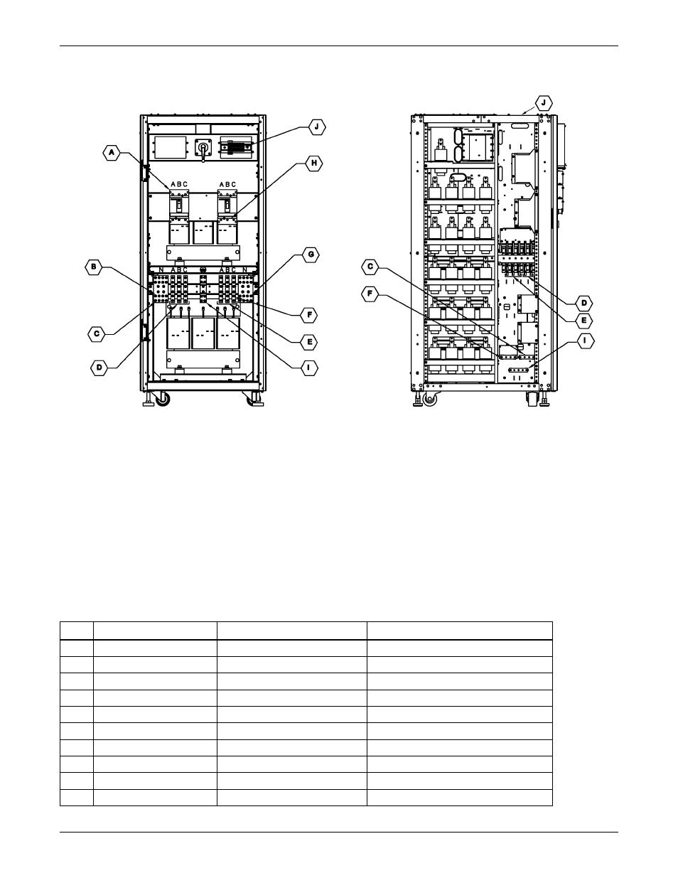
Figure 37 Maintenance Bypass interconnection
Table 12
Liebert-supplied interconnect wiring for Maintenance Bypass Cabinet
Run
From
To
Conductors
A
Utility AC source
Maintenance
Ph A, B, C bypass/ transformer cabinet
B
Utility AC source
Maintenance
Neutral bypass/ transformer cabinet
C
Maintenance
UPS module AC input
Neutral - UPS Input
D
Maintenance
UPS module AC input
Ph A, B, C - UPS Input
E
UPS module AC output
Maintenance
Ph A, B, C - UPS Output
F
UPS module AC output
Maintenance
Neutral - UPS Output
G
Maintenance
Load AC connection
Neutral bypass cabinet
H
Maintenance
Load AC connection
Ph A, B, C bypass cabinet
I
Utility AC source
All ground connections
Ground
J
Monitoring terminal block
UPS Parallel Logic Board (M3)
Bypass contacts
NOTES
1. All Liebert-supplied cable must be repositioned prior to and while the cabinets are being placed in their
final installed location.
2. All interconnection hardware supplied by Liebert.
3. AC connections must be made to the UPS module before attaching maintenance bypass/transformer
cabinet to UPS module.
4. Utility AC source neutral not required for maintenance bypass/transformer cabinet types D, E, M, N.
5. All cabling will be field-supplied when maintenance bypass/transformer cabinet is configured as stand-
alone cabinet.
6. Maintenance bypass/transformer cabinets must attach to the left side only.
7. Refer to the individual drawing of each piece of equipment for additional details.
Refer to Table 12 for key to interconnection
Maintenance Bypass/Transformer Cabinet
front view without front door and panel
UPS Module
left-side view without side panel