5 power cables, 6 parallel control cables, Parallel system control cables – Emerson Liebert NX 10-30kVA User Manual
Page 42: Auxiliary dry contact cables, Power cables, Parallel control cables
Option Installations
34
5.3.5 Power Cables
Wiring of power cables is similar to that of single-module system (See 2.1 - Power Cabling). The
bypass sources of all modules should be the same, and the outputs should be connected altogether cor-
rectly.
Power cables will be supplied by customer. Power cables to the UPS’s of the 1+N paralleling cabinet
must be routed through either the top or bottom entry access of the UPS.
For systems using a parallel cabinet, see Figures 38 and 40 through 42 for power cable terminations.
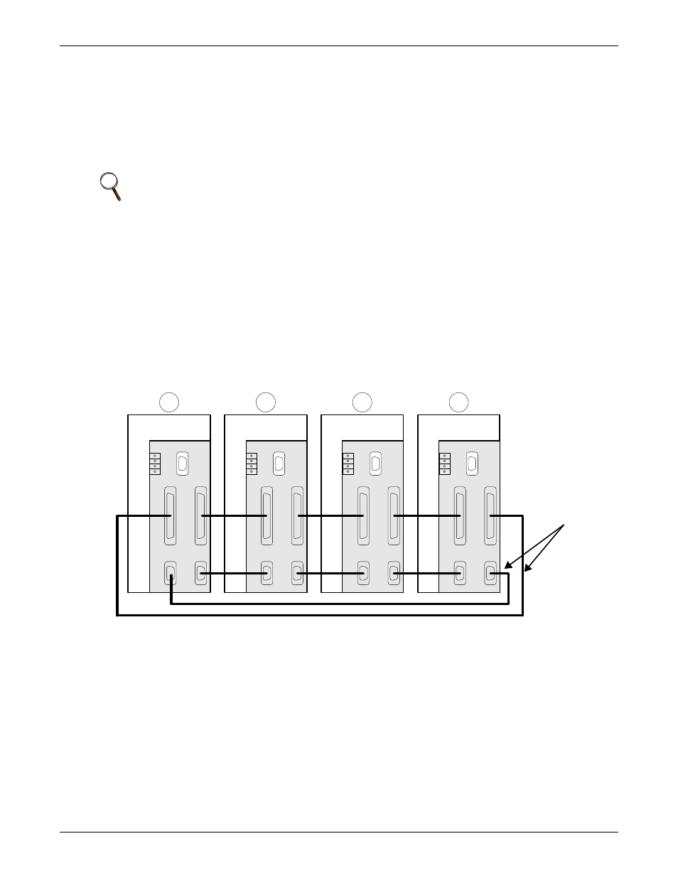
5.3.6 Parallel Control Cables
Parallel System Control Cables
Make the connections listed below on the parallel logic board (M3) inside the NX. (See Figure 32 for
the location of the parallel logic board):
Shielded and double-insulated control cables available in lengths of up to 100 feet (30m) must be
interconnected in a ring configuration between UPS modules as shown below. The ring configuration
ensures high reliability of the control (refer to Figure 23).
See Figure 25 for dry contacts control cable wiring diagram.
Figure 23 Connecting '1+N' system parallel control cables
Auxiliary Dry Contact Cables
The external output breaker of each UPS must have Normally Open auxiliary contacts. These con-
tacts must be wired to connector X3 on the Parallel Logic Board (M3). See Figure 24.
NOTE
The length and specifications of power cables including the bypass input cables and UPS
output cables should be the same, thus the load can be shared evenly in bypass mode.
X1-1
X1-2
X2-2 X2-1
Parallel Board
X4
X3
P5
P3
P4
P1
P2
X1-1
X1-2
X2-2 X2-1
Parallel Board
X4
X3
P5
P3
P4
P1
P2
X1-1
X1-2
X2-2 X2-1
Parallel Board
X4
X3
P5
P3
P4
P1
P2
X1-1
X1-2
X2-2 X2-1
Parallel Board
X4
X3
P5
P3
P4
P1
P2
1
2
3
4
UPS
Interconnecting
Cables