0 installation drawings, Nstallation, Rawings – Emerson Liebert NX 10-30kVA User Manual
Page 52: 0 - installation drawings, Figure 30
Installation Drawings
44
6.0
I
NSTALLATION
D
RAWINGS
The diagrams in this section illustrate the key mechanical and electrical characteristics of the NX
UPS System cabinets.
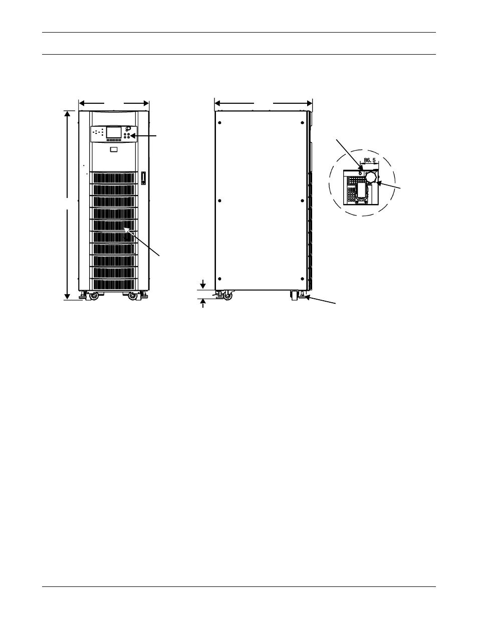
Figure 30 Dimensional view- front and left side views
1. All dimensions are in millimeters.
2. A minimum of 24 inches clearance above the unit is required for air exhaust.
3. Installation and service access required. Left-side access recommended for maximum ease of
installation.
4. Keep cabinet within 15 degrees of vertical while handling.
5. Top and bottom cable entry available through removal access plates. Remove punch to suit conduit size
and replace.
6. Unit bottom is structurally adequate for forklift handling.
7. Open door to replace air filter, washable type, size 354x314.
8. Threaded mounting holes used for seismic anchoring or floor stand. Note: If a floor stand is used, the
weight of the unit must be supported under all casters.
9. Each mounting location is supported by two 10 GA. (.135”) galvanized steel. The threaded 12mm insert
is approximately 3/4” deep. Mounting bolts must be threaded into unit.
10. Includes side panel. Refer to Detail A for dimension to frame with side panel removed. Side panels are
removed between adjacent units that are bolted together.
11. Adjustable stops are not designed to carry the full weight of the cabinet. Finger-tighten stop against the
floor, then tighten with a wrench less than two turns for friction against the floor.
Monitoring
Panel
Air intake area.
Do not block
air filter.
FRONT VIEW
LEFT SIDE VIEW
10mm dia. threaded
mounting holes
Detail “A” Rear of unit
shown without side panel
Adjustable Stops
825
600
1600
90
Leveler