Figure 38 nx 1+1 parallel cabinet interconnections, Table 13 liebert-supplied interconnect wiring, Table 13 – Emerson Liebert NX 10-30kVA User Manual
Page 59: Liebert-supplied interconnect wiring, E figures 38 an
Installation Drawings
51
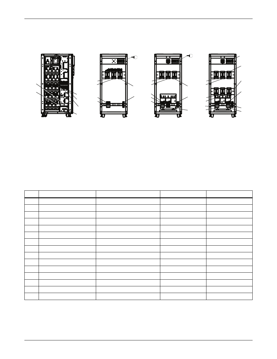
Figure 38 NX 1+1 parallel cabinet interconnections
Table 13
Liebert-supplied interconnect wiring
Run
From
To
Conductors
Cabinet Type
A
Utility AC Source
Paralleling Cabinet
PH A, B, C - Bypass
BR0, CR1, DR1
B
Utility AC Source
Paralleling Cabinet
Neutral - Bypass
BR0, CR1, DR1
C
Utility AC Source
UPS Module AC Input
PH A,B,C - UPS
A00, BR0
D1
UPS #1 Module AC Output
Paralleling Cabinet
PH A, B, C - UPS
A00, BR0, CR1, DR1
D2
UPS #2 Module AC Output
Paralleling Cabinet
PH A, B, C - UPS
A00, BR0, CR1, DR1
E
Utility AC Source
UPS #1 Module AC Input
Neutral - UPS Input
A00, BR0, CR1, DR1
E2
Utility AC Source
UPS #1 Module AC Input
Neutral - UPS Input
A00, BR0, CR1, DR1
F1
Paralleling Cabinet
UPS #1 Module AC Output
Neutral - UPS Output
A00, BR0, CR1, DR1
F2
Paralleling Cabinet
UPS #1 Module AC Output
Neutral - UPS Output
A00, BR0, CR1, DR1
G
Paralleling Cabinet
Load AC Connection
Neutral - Load
A00, BR0, CR1, DR1
H
Paralleling Cabinet
Load AC Connection
PH A, B, C - Load
A00, BR0, CR1, DR1
I
Utility AC Source
All Ground Connections
Ground
A00, BR0, CR1, DR1
J
Monitoring Terminal Block
UPS Parallel Logic Board (M3)
Auxiliary Contacts
A00, BR0, CR1, DR1
K1
UPS #1 Module AC Input
Paralleling Cabinet
PH A, B, C - UPS
CR1, DR1
K2
UPS #1 Module AC INPUT
Paralleling Cabinet
PH A, B, C - UPS
CR1, DR1
G
Type A00
D1
D2
H
J
I
Type BR0
G
B
A
I
J
Type DR1 & CR1
I
B
H
A
J
E1,E2
D1,D2
I
K1,K2
C
F1,F2
F1, F2
F1,F2
D1
D2
H
F1,F2
D1
D2
G
K1
K2
E1,E2
1+1 Parallel Cabinet
(Front View Without Front Door and Panel)
UPS Module Left Side View
(Without Side Panel)
NOTES:
1. All Liebert-supplied cable will need to be repositioned prior to and while setting the cabinets in their
installed location.
2. All interconnection cable and hardware supplied by others.
3. AC connections must be made to the UPS modules before attaching paralleling cabinet to UPS modules.
4. Utility AC source neutral not required for maintenance bypass/transformer cabinet type CR1.
5. Paralleling cabinets must between both UPS modules.
6. Refer to the individual drawing of each piece of equipment for additional details