2 operation mode – Epson S1C88650 User Manual
Page 95
S1C88650 TECHNICAL MANUAL
EPSON
87
5 PERIPHERAL CIRCUITS AND THEIR OPERATION (Programmable Timer)
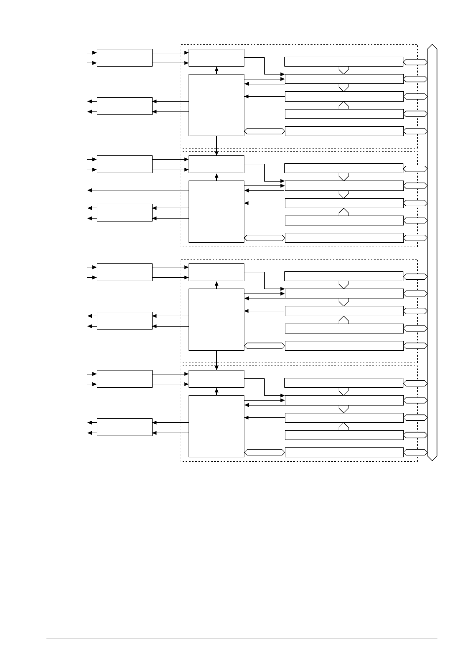
Fig. 5.10.1.2 Configuration of 16-bit programmable timer (Timers 4–7)
Data bus
8-bit reload data register (RDR4)
8-bit down counter (PTM4)
8-bit compare data register (CDR4)
Timer 4 control registers
Control circuit
Clock selection
circuit
Prescaler/clock
control circuit
Comparator
Underflow
Underflow signal
INCL4
f
OSC3
/f
OSC1
Input port (K06)
EXCL2
Underflow
interrupt
Compare match
interrupt
Compare match
Timer 4
Interrupt circuit
8-bit reload data register (RDR5)
8-bit down counter (PTM5)
8-bit compare data register (CDR5)
Timer 5 control registers
Control circuit
Clock selection
circuit
Prescaler/clock
control circuit
Comparator
Underflow
INCL5
f
OSC3
/f
OSC1
Input port (K06)
EXCL2
Underflow
interrupt
Compare match
interrupt
To LCD driver
Compare match
Timer 5
Interrupt circuit
8-bit reload data register (RDR6)
8-bit down counter (PTM6)
8-bit compare data register (CDR6)
Timer 6 control registers
Control circuit
Clock selection
circuit
Prescaler/clock
control circuit
Comparator
Underflow
Underflow signal
INCL6
f
OSC3
/f
OSC1
Input port (K07)
EXCL3
Underflow
interrupt
Compare match
interrupt
Compare match
Timer 6
Interrupt circuit
8-bit reload data register (RDR7)
8-bit down counter (PTM7)
8-bit compare data register (CDR7)
Timer 7 control registers
Control circuit
Clock selection
circuit
Prescaler/clock
control circuit
Comparator
Underflow
INCL7
f
OSC3
/f
OSC1
Input port (K07)
EXCL3
Underflow
interrupt
Compare match
interrupt
Compare match
Timer 7
Interrupt circuit
5.10.2 Operation mode
Timers 0 and 1, Timers 2 and 3, Timers 4 and 5, or
Timers 6 and 7 can be used as two channels of 8-bit
timers or one channel of 16-bit timer. Two kinds of
operation modes are provided corresponding to
this configuration, and it can be selected by the 8/
16-bit mode selection registers MODE16_A (for
Timer 0–1) through MODE16_D (for Timer 6–7).
When "0" is set to the MODE16_A register, Timers 0
and 1 enter the 8-bit mode (8-bit
×
2 channels) and
when "1" is set, they enter the 16-bit mode (16-bit
×
1 channel).
In the 8-bit mode, Timers 0 and 1 can be controlled
individually.
In the 16-bit mode, the underflow signal of Timer 0
is used as the input clock of Timer 1 so that the
down counters operate as a 16-bit counter.
The timer in the 16-bit mode is controlled with the
control registers for Timer 0 except for the clock
output.
MODE16_B through MODE16_D have the same
function.
Figure 5.10.2.1 shows the timer configuration
depending on the operation mode and Table
5.10.2.1 shows the configuration of the control
registers.