8 serial interface, 1 configuration of serial interface, 2 switching of terminal functions – Epson S1C88650 User Manual
Page 69
S1C88650 TECHNICAL MANUAL
EPSON
61
5 PERIPHERAL CIRCUITS AND THEIR OPERATION (Serial Interface)
5.8 Serial Interface
5.8.1 Configuration of serial interface
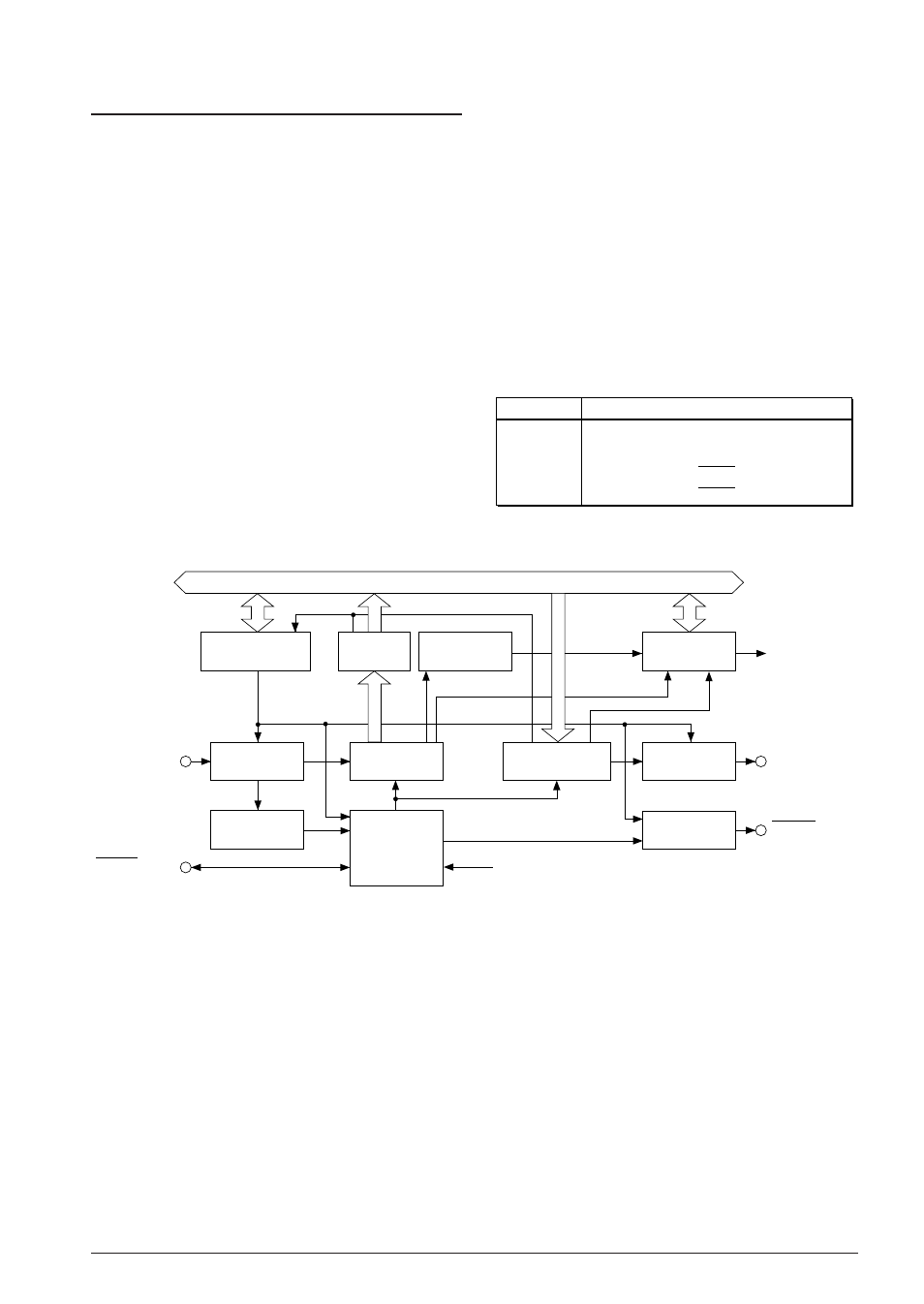
The S1C88650 incorporates a full duplex serial
interface (when asynchronous system is selected)
that allows the user to select either clock synchro-
nous system or asynchronous system.
The data transfer method can be selected in soft-
ware.
When the clock synchronous system is selected, 8-
bit data transfer is possible.
When the asynchronous system is selected, either 7-
bit or 8-bit data transfer is possible, and a parity
check of received data and the addition of a parity
bit for transmitting data can automatically be done
by selecting in software.
Figure 5.8.1.1 shows the configuration of the serial
interface.
Data bus
SOUT(P11)
Serial I/O control
& status register
Received
data buffer
Interrupt
control circuit
Serial input
control circuit
Received data
shift register
Transmitting data
shift register
Serial output
control circuit
SIN(P10)
Clock
control circuit
READY output
control circuit
SCLK(P12)
Error detection
circuit
SRDY(P13)
Start bit
detection circuit
Programmable timer 1 underflow signal
Interrupt
request
Fig. 5.8.1.1 Configuration of serial interface
5.8.2 Switching of terminal functions
Serial interface input/output terminals, SIN, SOUT,
_________
_________
SCLK and SRDY are shared with I/O ports P10–
P13. In order to utilize these terminals for the serial
interface input/output terminals, "1" must be
written to the ESIF register.
At initial reset, these terminals are set as I/O port
terminals.
The direction of I/O port terminals set for serial
interface input/output terminals are determined by
the signal and transfer mode for each terminal.
Furthermore, the settings for the corresponding I/
O control registers for the I/O ports become
invalid.
Table 5.8.2.1 Configuration of input/output terminals
Terminal
When serial interface is selected
P10
P11
P12
P13
SIN
SOUT
SCLK
SRDY
* The terminals used may vary depending on the transfer mode.