2 initial settings after initial reset – Epson S1C88650 User Manual
Page 25
S1C88650 TECHNICAL MANUAL
EPSON
17
4 INITIAL RESET
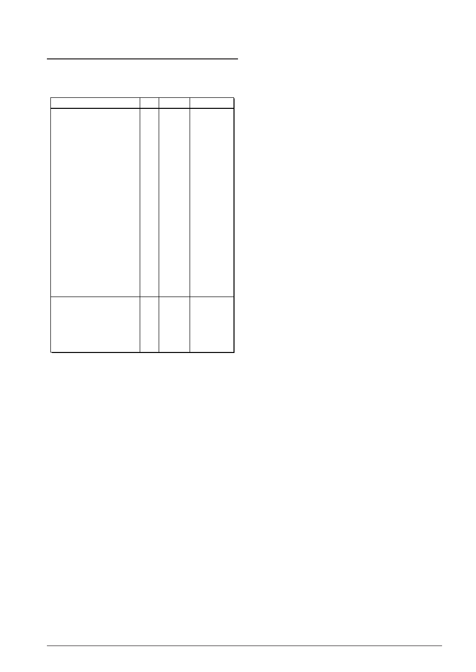
4.2 Initial Settings After Initial Reset
The CPU internal registers are initialized as follows
during initial reset.
Table 4.2.1 Initial settings
Register name
Code
Setting value
Data register A
Data register B
Index (data) register L
Index (data) register H
Index register IX
Index register IY
Program counter
Stack pointer
Base register
Zero flag
Carry flag
Overflow flag
Negative flag
Decimal flag
Unpack flag
Interrupt flag 0
Interrupt flag 1
New code bank register
Code bank register
Expand page register
Expand page register for IX
Expand page register for IY
A
B
L
H
IX
IY
PC
SP
BR
Z
C
V
N
D
U
I0
I1
NB
CB
EP
XP
YP
Undefined
Undefined
Undefined
Undefined
Undefined
Undefined
Undefined
Undefined
Undefined
0
0
0
0
0
0
1
1
01H
Undefined
00H
00H
00H
Bit length
8
8
8
8
16
16
16
16
8
1
1
1
1
1
1
1
1
8
8
8
8
8
*
*
*
Reset exception processing loads the preset
values stored in 0 bank, 0000H–0001H into the
PC. At the same time, 01H of the NB initial
value is loaded into CB.
Initialize the registers which are not initialized at
initial reset using software.
Since the internal RAM and display memory are
not initialized at initial reset, be sure to initialize
using software.
The respectively stipulated initializations are done
for internal peripheral circuits. If necessary, the
initialization should be done using software.
For initial value at initial reset, see the sections on
the I/O memory map and peripheral circuit
descriptions in the following chapter of this
manual.