Blackmagic Design URSA Mini Pro 12K (PL) User Manual
Page 207
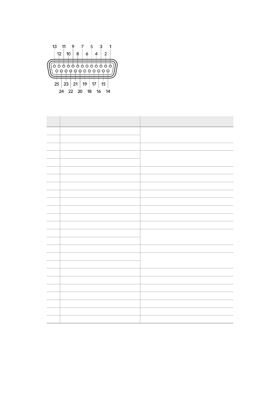
The external view of the 25 pin ‘intercom/tally’ connector
Talkback Pinout Diagram
Pins
Signal
Specifications
1
ENG(R) IN+
Engineering channel input
0dBu balanced
2
ENG(R) IN-
3
ENG GND
GND for ENG
4
ENG(T) OUT +
Engineering channel output
0dBu balanced
5
ENG(T) OUT -
6
PGM IN+
-20dBu
7
PGM IN-
-20dBu
8
PGM GND
-20dBu
9
GND
GND for aux
10
N/C
–
11
Red Tally IN
On = 5-24Vdc, Off= 0Vdc
12
Red Tally GND
–
13
GND
Chassis GND
14
PROD(R) IN+
Production channel input
0dBu balanced
15
PROD(R) IN-
16
PROD GND
–
17
PROD(T) OUT+
Production channel output
0dBu balanced
18
PROD(T) OUT-
19
N/C
–
20
N/C
–
21
N/C
–
22
N/C
–
23
N/C
–
24
Green Tally IN
On = 5-24Vdc, Off= 0Vdc
25
Green Tally GND
–
207
Studio Unit Connections