13 filtering contours (fcl 2 function), Function – HEIDENHAIN iTNC 530 (340 49x-03) User Manual
Page 547
HEIDENHAIN iTNC 530
547
9.13 Filt
er
ing Cont
ours (FCL
2
F
unction)
9.13 Filtering Contours
(FCL 2 Function)
Function
With this TNC function you can filter contours that were created on
offline programming stations and contain only straight line segments.
The filter smoothes the contour, which generally permits faster and
jerk-free machining.
After you have entered the filter settings, the TNC generates a new
program, with filtered contours, from the original program.
8
Select the program you want to filter.
8
Shift the soft-key rows until the CONVERT
PROGRAM soft key appears.
8
Select the soft-key row with functions for converting
programs.
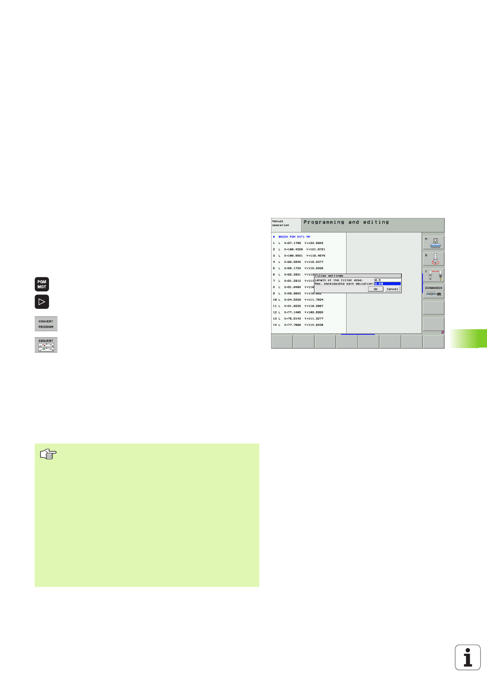
8
Select the filter function. The TNC opens a pop-up
window for the definition of the filter settings.
8
Enter the length of the filter range in mm (inches for
inch programs). Starting from the point in question,
the filter range defines the actual length on the
contour (before and after the point) within which the
TNC is to filter the points. Confirm with the ENT key.
8
Enter the maximum permitted path deviation in mm
(inches for inch programs). Confirm the tolerance
value, which is the most that the contour may deviate
from the original contour, with ENT the key.
Depending on the filter settings, the newly generated file
may contain significantly more points (straight-line blocks)
than the original file.
The maximum permitted path deviation should not
exceed the actual point separation, otherwise the TNC
linearizes the contour excessively.
The program to be filtered must not contain any NC blocks
with M91 or M92.
The name of the file created by the TNC consists of the
old file name and the extension _flt. Example:
File name of the program whose machining direction is
to be reversed: CONT1.H
File name of the filtered program generated by the TNC:
CONT1_flt.h