5 tilting the working plane, Application, function – HEIDENHAIN iTNC 530 (340 420) ISO programming User Manual
Page 52
52
2 Manual Operation and Setup
2.5 Tilting the W
o
rk
ing Plane
2.5 Tilting the Working Plane
Application, function
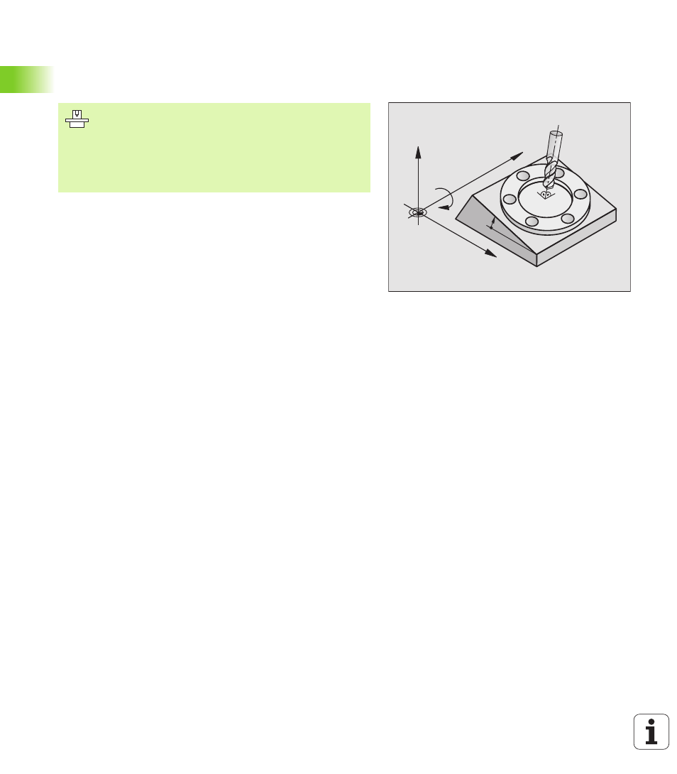
The TNC supports the tilting functions on machine tools with swivel
heads and/or tilting tables. Typical applications are, for example,
oblique holes or contours in an oblique plane. The working plane is
always tilted around the active datum. The program is written as usual
in a main plane, such as the X/Y plane, but is executed in a plane that
is tilted relative to the main plane.
There are two functions available for tilting the working plane:
n
3-D ROT soft key in the Manual mode and Electronic Handwheel
mode, see “Activating manual tilting,” page 55.
n
Tilting under program control, Cycle G80 WORKING PLANE in the part
program (see “WORKING PLANE (Cycle G80)” on page 359).
The TNC functions for “tilting the working plane” are coordinate
transformations in which the working plane is always perpendicular to
the direction of the tool axis.
When tilting the working plane, the TNC differentiates between two
machine types:
n
Machine with tilting tables
n
You must tilt the workpiece into the desired position for
machining by positioning the tilting table, for example with a G0
block.
n
The position of the transformed tool axis does not change in
relation to the machine-based coordinate system. Thus if you
rotate the table—and therefore the workpiece—by 90° for
example, the coordinate system does not rotate. If you press
the Z+ axis direction button in the Manual Operation mode, the
tool moves in Z+ direction.
n
In calculating the transformed coordinate system, the TNC
considers only the mechanically influenced offsets of the
particular tilting table (the so-called “translational” components).
The functions for tilting the working plane are interfaced
to the TNC and the machine tool by the machine tool
builder. With some swivel heads and tilting tables, the
machine tool builder determines whether the entered
angles are interpreted as coordinates of the rotary axes or
as angular components of a tilted plane. Refer to your
machine manual.
X
Z
Y
B
10°