Figure 3.6, Wireless sensor configuration – RLE Wi-MGR V.1.6 User Manual
Page 30
30
Wi-MGR User Guide
800.518.1519
3
Web Interface
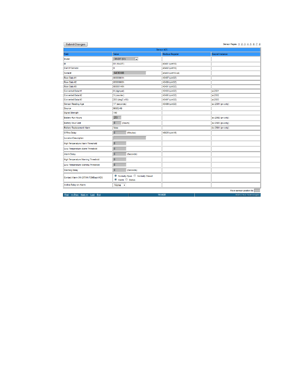
Click the number on the left side of the sensor row to edit individual sensor properties.
Figure 3.6
Wireless Sensor Configuration
For each sensor, all fields in gray are editable. All other fields are for reference only. To the
right of the Value field is the corresponding Modbus Register column for slave data output
from that sensor. To the right of that is the BACnet Instance column for slave interface to a
Building Management System.
NOTE
When the desired edits have been made, click the Submit Changes button to save
the changes. If the Submit Changes button is not selected, the new configuration will
not be updated and saved.