Figure 2.1, 24vdc power supply connection, Figure 2.2 – RLE Wi-MGR V.1.6 User Manual
Page 14: Wi-mgr antennae
14
Wi-MGR User Guide
800.815.1519
2
Getting Started
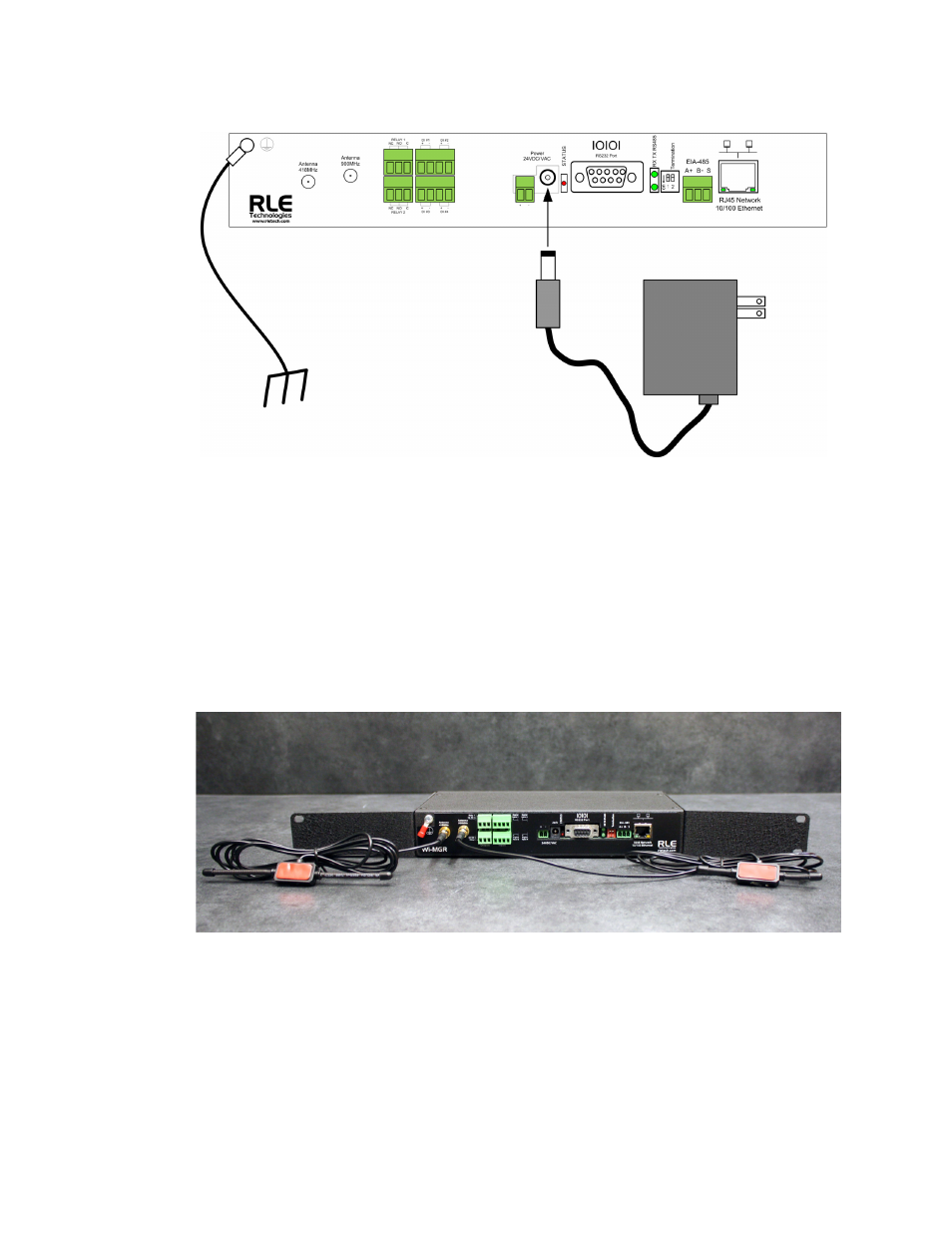
Figure 2.1
24VDC Power Supply Connection
If the EIA-485 port will be used for Modbus RTU communication, RLE Technologies
recommends an 18AWG shielded twisted pair stranded copper wire for the connection, using
no more than 2000 feet (609.6m) of wire at this specification. If longer runs are needed, please
contact RLE Technologies.
The Wi-MGR is shipped with a 418 MHz, 6-foot cable antenna and a 900 MHz, 6-foot cable
antenna. The 418 MHz antenna has longer shafts; the 900 MHz antenna has shorter shafts.
Plug each antenna into its appropriate jack on the front of the Wi-MGR.
Figure 2.2
Wi-MGR Antennae
418 MH
Z
900 MH
Z
A
NTENNA
A
NTENNA